
Vehicle control system and method

Inactive Publication Date: 2019-05-09
HL KLEMOVE CORP
View PDF10 Cites 7 Cited by
  • Summary
  • Abstract
  • Description
  • Claims
  • Application Information

AI Technical Summary

Benefits of technology

The present patent is about a vehicle control system and method that can predict collisions between peripheral vehicles and prevent secondary accidents. It also works with an autonomous emergency braking system and a lane keeping assist system to improve safety and prevent sensitive operation prevention-based accidents on the highway. In summary, the system can predict and prevent accidents, especially in situations where there are many vehicles around a vehicle.

Problems solved by technology

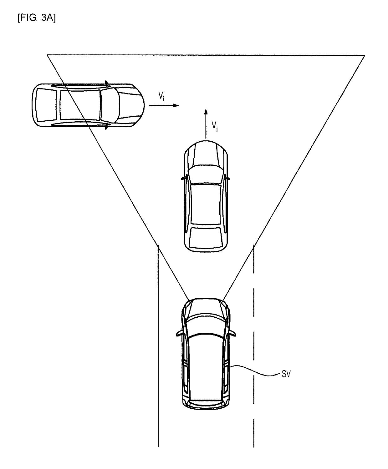
However, the conventional forward collision warning and mitigation system performs vehicle control by calculating only a degree of collision risk between the host vehicle and the preceding vehicle and thus has a difficulty in preventing a secondary accident or a pile-up by coping with a dangerous situation, in which movement of peripheral vehicles is not predicted, such as collision between peripheral vehicles, in advance.
A highway is a road prepared so that vehicles drive thereon at a high speed and, in case of an accident on the highway, a major accident may be caused.
However, in order not to provide inconvenience to a driver by reducing a braking amount in a wrong vehicle sensing situation or a proximate overtaking situation, the conventional AEB system performs stepwise braking control in which designated warning and braking distances are generally given regardless of attributes of a road on which the vehicle drives and full braking of 1.0 g is carried out after pre-braking of 0.2 g, as exemplarily shown in FIGS. 3A and 3B, thus being limited in terms of avoidance of a dangerous situation when the vehicle drives on a highway other than a general road.
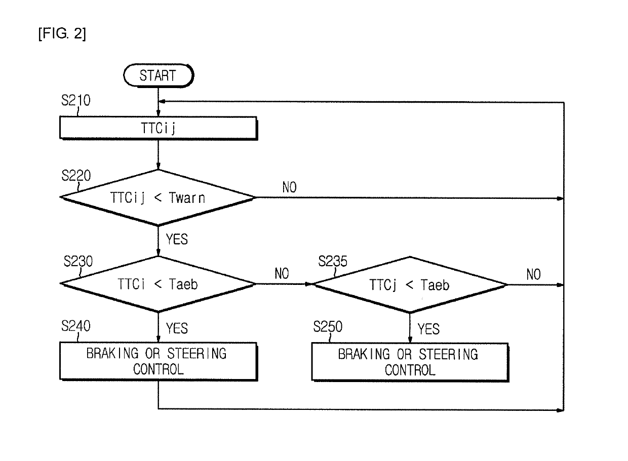
The degree of collision risk may be a collision required time taken to reach collision between two objects.

Method used


Image

  • Vehicle control system and method
  • Vehicle control system and method
  • Vehicle control system and method

Examples


Embodiment Construction

[0035]Advantages and features of the present disclosure and a method of achieving the advantages and features of the present disclosure will be clearly understood from embodiments described hereinafter in conjunction with the accompanying drawings. However, the present disclosure is not limited to the following embodiments and may be realized in various different forms. These embodiments are provided only to completely disclose the present disclosure and for a person having ordinary skill in the art to which the present disclosure pertains to completely understand the category of the disclosure. That is, the present disclosure is defined only by the claims. The same reference numbers will be used throughout this specification to refer to the same parts.

[0036]Hereinafter, a vehicle control system and method in accordance with the present disclosure will be described in detail with reference to the accompanying drawings.

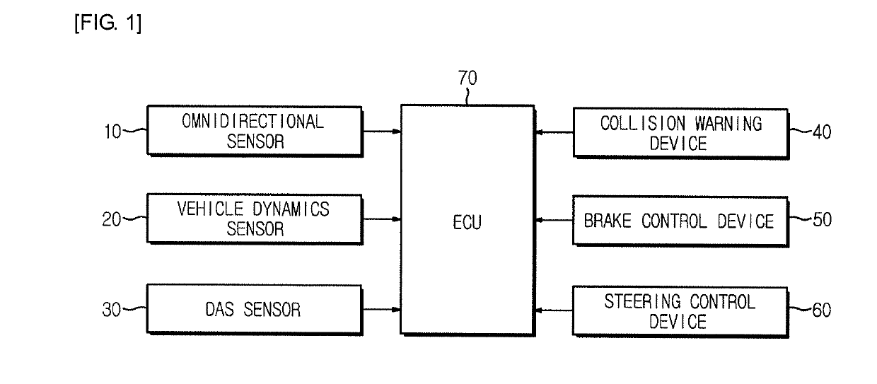
[0037]FIG. 1 is a block diagram schematically illustrating an ove...


PUM


Abstract

A vehicle control system and method through peripheral collision situation prediction are disclosed. The vehicle control system includes omnidirectional sensors configured to sense distances and relative speeds between a host vehicle and peripheral objects and to transmit the distances and the relative speeds to an electronic control unit, vehicle dynamics sensors configured to sense a driving speed of the host vehicle and to transmit the driving speed to the electronic control unit, and the electronic control unit configured to receive sensing signals from the omnidirectional sensors and the vehicle dynamics sensors, to predict collision risk between a plurality of the peripheral objects and to execute control so as to perform braking avoidance and steering avoidance of the peripheral objects, thus being capable of preventing a secondary accident or a pile-up.

Description

CROSS-REFERENCE TO RELATED APPLICATION[0001]This application is based on and claims priority under 35 U.S.C. § 119 to Korean Patent Application Nos. 10-2017-0146233, filed on Nov. 3, 2017, and 10-2018-0023800, filed on Feb. 27, 2018 in the Korean Intellectual Property Office, the disclosure of which is incorporated by reference in its entirety.BACKGROUND1. Field[0002]Embodiments of the present disclosure relate to a vehicle control system and method through peripheral collision situation prediction, and more particularly to a vehicle control system and method through peripheral collision situation prediction which may prevent secondary accidents by predicting collision situations around the vehicle.[0003]Further, embodiments of the present disclosure relate to an autonomous emergency braking system and method interworking with a highway driving assist (HDA) system, and more particularly to an autonomous emergency braking system and method interworking with a highway driving assistan...

Claims


Application Information

Patent Timeline
IPC IPC(8): B60W30/09B60W10/20B60W10/18B60W30/095B60W30/14B60W30/12
CPCB60W30/09B60W10/20B60W10/18B60W30/0956B60W30/143B60W30/12B60W2550/302B60W2550/308B60W2550/141B60W2710/18B60W2710/20B60W30/0953B60W2554/4042B60W2554/801B60W2552/05B60W2554/804
Inventor LEE, SANG YEOB
Owner HL KLEMOVE CORP
Learn More