Quick-release structure

a quick-release, structure technology, applied in the direction of axle suspension, hub, cycle equipment, etc., can solve the problems of reducing service life, reducing market competitiveness, and affecting the service life of the spanner rod, so as to reduce the service life, reduce the cost of manufacturing, and lose the effect of market competitiveness

Active Publication Date: 2019-05-09
SHUN XIN CO LTD
View PDF12 Cites 2 Cited by
  • Summary
  • Abstract
  • Description
  • Claims
  • Application Information

AI Technical Summary

Benefits of technology

[0005]In view of this, in order to solve the problems in the prior art that a conventional quick-release structure is prone to repeatedly press a frame fork to cause damage to the frame fork and the quick-release structure and hence reduce the service life, and components are too complicated to result in high manufacturing cost and hence lose the market competitiveness, the invention provides a quick-release structure, comprising: a shaft lever having a shaft lever external thread at one end thereof and a shaft lever internal thread at the other end thereof; a fixed seat sheathed on the shaft lever in a non-rotatable manner relative to each other, wherein the fixed seat has an annular fixed seat engaging tooth on one end face thereof; a movable seat having an axially penetrating perforation, wherein the movable seat has an annular movable seat engaging tooth on one end face thereof, and the movable seat engaging tooth faces the fixed seat engaging tooth of the fixed seat; a spring abutting between the fixed seat and the movable seat; a spanner rod having a pivoting hole; and a connecting shaft, one end of which abuts on the spanner rod, and the other end of which has a connecting shaft external thread and sequentially passes through the pivoting hole of the spanner rod, the perforation of the movable seat and the spring so as to be screwed into the shaft lever internal thread of the shaft lever. When the spanner rod presses the movable seat, the movable seat engaging tooth of the movable seat is engaged with the fixed seat engaging tooth of the fixed seat; and when the spanner rod releases the movable seat, the movable seat is pushed away by the spring such that the movable seat engaging tooth is disengaged from the fixed seat engaging tooth. Accordingly, the above arrangement can achieve the effects of preventing the components and the bicycle fork from being easily damaged, increasing the service life, simplifying the components, providing low manufacturing cost and having the market competitiveness.

Problems solved by technology

However, such quick-release structure screwed and locked to the frame by means of threads has the disadvantages that the tension can only be adjusted by a one-side spanner rod, and thus the position of the spanner rod cannot be easily controlled.
If the spanner rod is orientated downwards, the quick-release structure may be disengaged due to impact on the spanner rod by foreign matter, but if the spanner rod is forcibly secured upwards, the engagement may be too loose or too tight.
However, when the disengagement and engagement of the fine-adjustable unit result in gaps between such quick-release structure and the frame fork and then the quick-release structure is pressed again, actually the frame fork is tightly pressed, released and then tightly pressed, which is the process of repeated secondary tight pressing for the frame fork, such that the frame fork and the quick-release structure are easily damaged after long-term use, thus reducing the service life.
Besides, the components of the fine-adjustable unit of such quick-release structure are too numerous and complicated, which not only results in higher manufacturing cost, but also hence increases the selling price, thereby losing the market competitiveness.

Method used


Image

  • Quick-release structure
  • Quick-release structure
  • Quick-release structure

Examples


Embodiment Construction

[0010]In order that the examiner can have a still further understanding and recognition of the features and characteristics of the invention, the following preferred embodiments will be listed and described below with reference to the drawings.

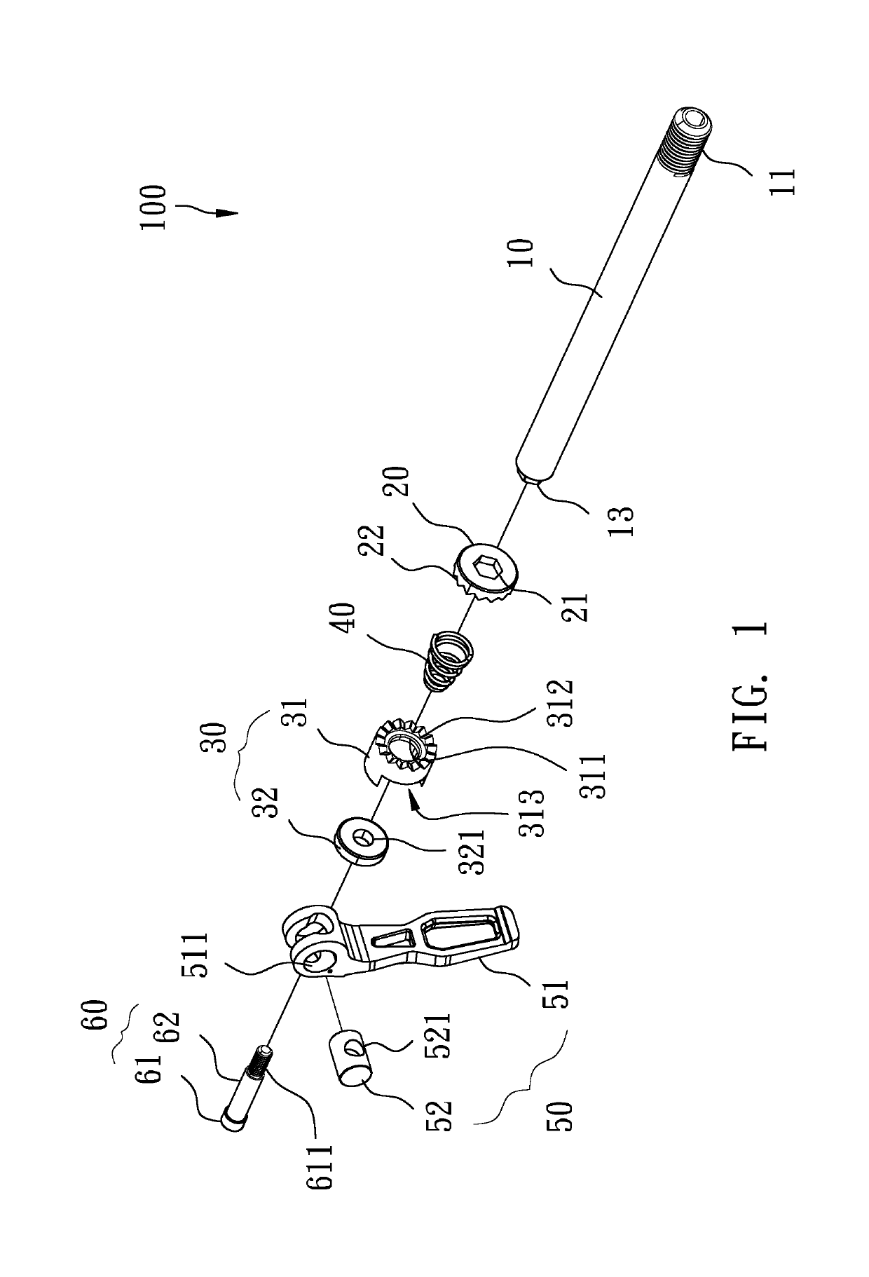
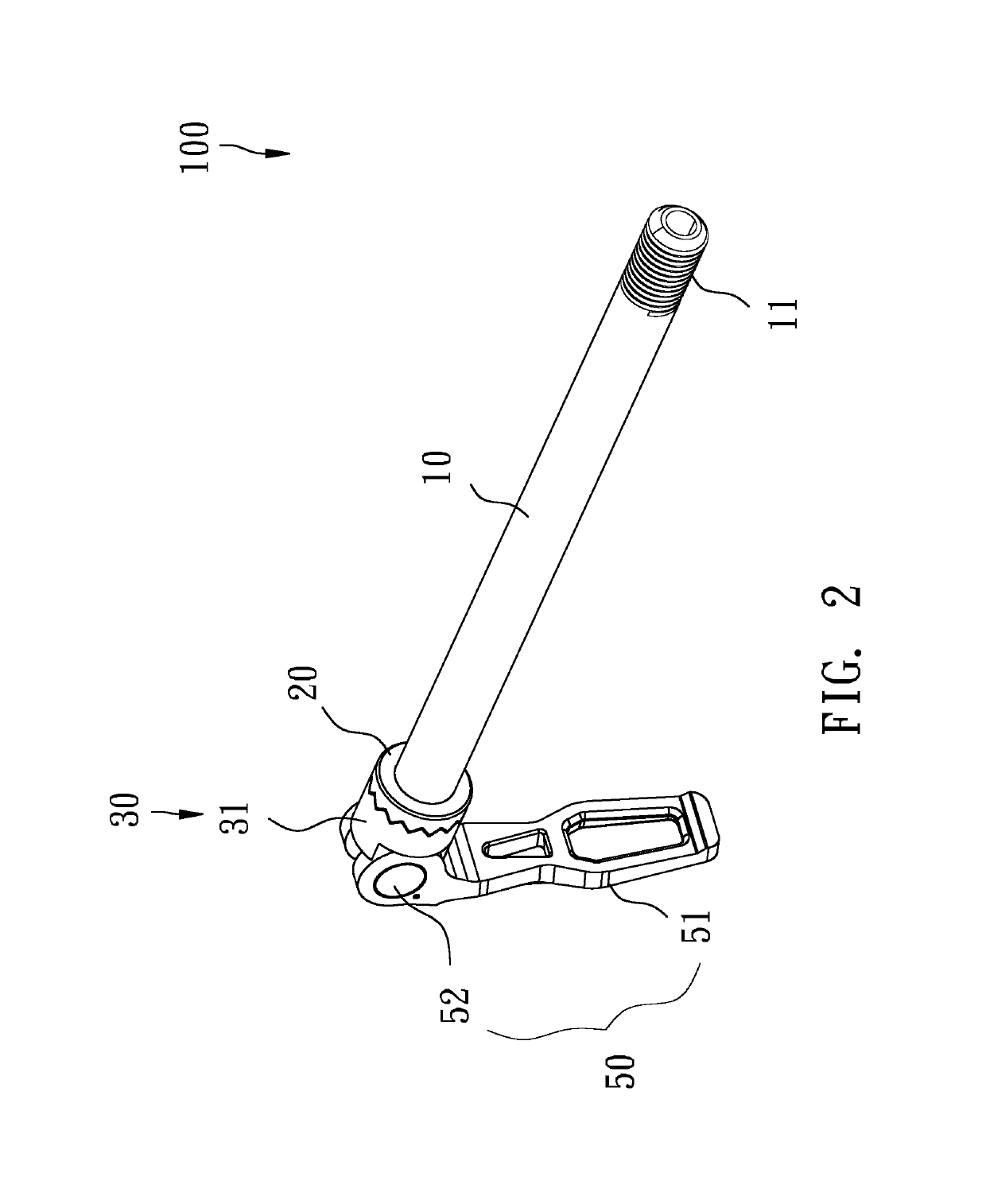
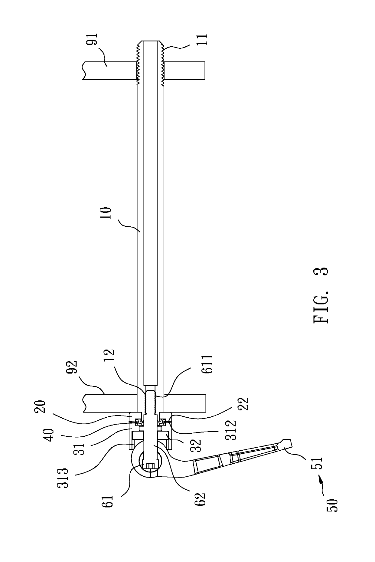
[0011]Referring to FIGS. 1 to 6, a quick-release structure 100 provided by a preferred embodiment of the invention mainly comprises a shaft lever 10, a fixed seat20, a movable seat 30, a spring 40, a spanner rod 50 and a connecting shaft 60.

[0012]Referring to FIGS. 1 to 3, the shaft lever 10 has a shaft lever external thread 11 on an outer circumferential surface of one end thereof and has a shaft lever internal thread 12 and a rotation limiting portion 13 at the other end thereof, wherein the rotation limiting portion 13 is located on the same end face as the shaft lever internal thread 12 and has a non-circular section. In the embodiment, the rotation limiting portion 13 is a hexagonal column.

[0013]Referring to FIGS. 1 to 3, the fixed seat 2...


PUM


Abstract

A quick-release structure has: a shaft lever having a shaft lever external thread at one end thereof and a shaft lever internal thread at the other end thereof; a fixed seat sheathed on the shaft lever in a non-rotatable manner relative to each other. The fixed seat has an annular fixed seat engaging tooth on one end face thereof; a movable seat having an axially penetrating perforation, wherein the movable seat has an annular movable seat engaging tooth on one end face thereof, and the movable seat engaging tooth faces the fixed seat engaging tooth of the fixed seat; a spring abutting between the fixed seat and the movable seat; a spanner rod having a pivoting hole; and a connecting shaft, one end of which abuts on the spanner rod, and the other end of which has a connecting shaft external thread.

Description

FIELD OF THE INVENTION[0001]The invention relates to a component of a bicycle, and more specifically to a quick-release structure.BACKGROUND OF THE INVENTION[0002]A quick-release structure of a bicycle is mainly used to allow quick assembling and disassembling of a wheel and a frame (or a fork on the frame).[0003]There are various types of bicycles such as mountain bicycles, snow bicycles, downhill bicycles and road bicycles. For a quick-release structure used in a mountain bicycle or a downhill bicycle requiring significant impact strength, an external thread is disposed at one end of a shaft lever and then directly screwed to an internal thread of a frame, thereby improving the impact strength. However, such quick-release structure screwed and locked to the frame by means of threads has the disadvantages that the tension can only be adjusted by a one-side spanner rod, and thus the position of the spanner rod cannot be easily controlled. If the spanner rod is orientated downwards, ...

Claims


Application Information

Patent Timeline
Patent Type & Authority Applications(United States)
IPC IPC(8): B60B27/02
CPCB60B27/026B60B27/023B60B35/004B60B2900/112B60B2900/115B60B2900/325B60B2900/3312B60B2900/531B62K25/02
Inventor CHANG, CHIN-CHAO
Owner SHUN XIN CO LTD
Why Eureka
Try Eureka