Security feature

Active Publication Date: 2019-05-02
ASSA ABLOY AB
View PDF0 Cites 5 Cited by
  • Summary
  • Abstract
  • Description
  • Claims
  • Application Information

AI Technical Summary

Benefits of technology

The present patent provides a photo-luminescent security feature for ID cards that is visibly different when viewed from opposite sides of the ID. The feature includes a cut out or hole in the clear non-laserable polycarbonate core layer sandwiched between layers of clear laserable polycarbonate. The laserable polycarbonate layer contains ultraviolet fluorescent ink that can be applied to the surface of the laserable polycarbonate layer that adjoins the core non-laserable layer or the opposite side of the laserable polycarbonate layer. An opaque layer is added to the outer surface of each laserable polycarbonate layer to block the transmission of UV light. White polycarbonate is an example of an opaque material, but other colors that are opaque are substutable. A window or cut out is formed in each opaque layer to align with the first cut out in the core layer. An outer layer of clear laserable polycarbonate is added to the outer surface of each opaque layer. The unique visual effect of the patent is that the cut out in the core layer is visible only when an ultraviolet light source is illuminated from the opposite side of the ID, providing a method for authenticating the veracity of the ID.

Problems solved by technology

Methods and devices for identifying people have matured over the years and have become more complex, particularly depending upon the purpose or context in which the identification is needed.
Higher stake situations compel higher levels of security.
However, counterfeiting operations have also evolved in their complexity to keep up with the countermeasures.
Moreover, because the process permits the indicium to be added following manufacture of the card, this type of added security feature may be more easily counterfeited.

Method used


Image

  • Security feature
  • Security feature
  • Security feature

Examples


first embodiment

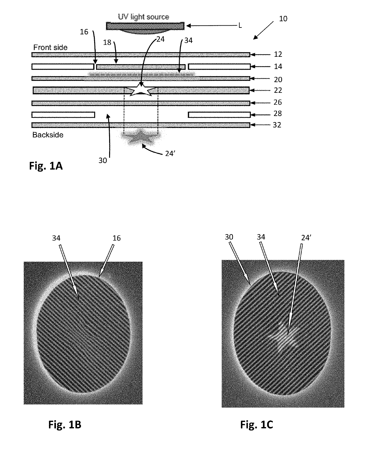
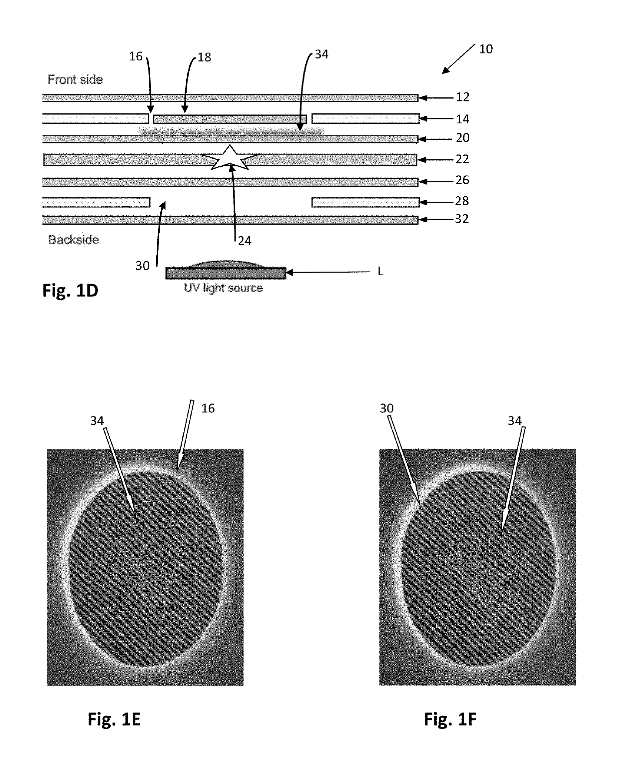
[0036]Turning to FIGS. 1A-1C, an identification device according to aspects of the present disclosure is illustrated. In this embodiment, an identification document in the form of a laminated substrate 10 with seven layers is described. All of the layers are polycarbonate. The top layer or front side of the substrate 12 is clear laserable polycarbonate that is 100μ thick. Moving toward the backside of the substrate, the next inner layer 14 is a white polycarbonate with a window or hole 16. The white polycarbonate is opaque and substantially non-transparent to visible light, UV light, IR light and other forms of light around the visible light spectrum. The hole 16 extends through the layer 14 and forms a first window 16. In this embodiment, the window 16 is oval shaped and is filled with an oval shaped clear laserable polycarbonate insert 18 of the same thickness. Alternatively, the clear laserable polycarbonate from surrounding layers, such as layer 12, can fill the window 16 when e...

third embodiment

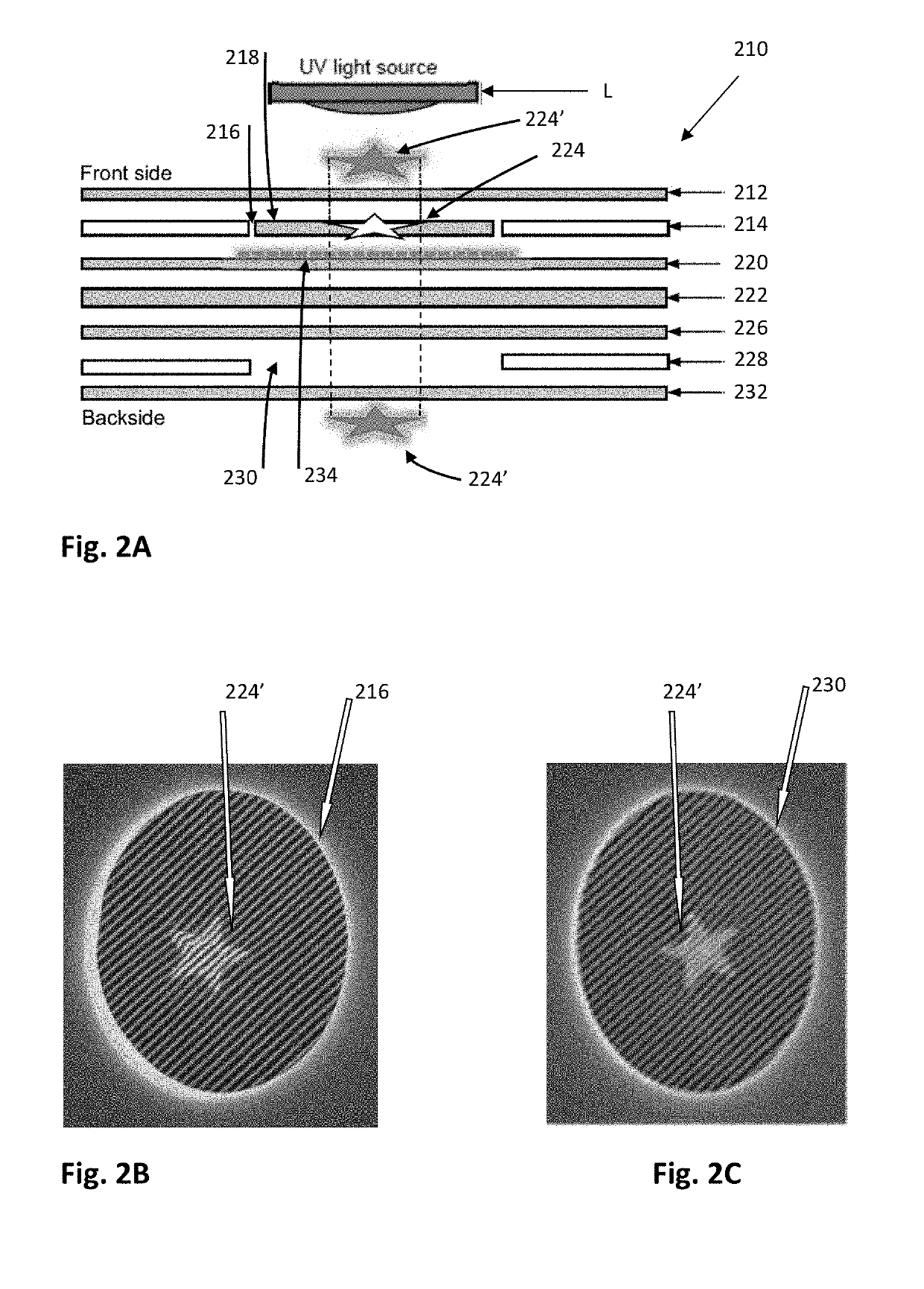
[0043]FIGS. 3A-3C illustrate a security feature utilized with an ID 310. This embodiment is similar to that illustrated in FIG. 2A. Using the embodiment of FIG. 2A as a reference, clear laserable polycarbonate layer 220 is removed and ultraviolet fluorescent ink 234 is moved to the front side surface of clear laserable polycarbonate layer 326. Thus, the area of ultraviolet fluorescent ink 334 is a farther distance from the cutout 324 in the embodiment of FIG. 3A compared to the ultraviolet fluorescent ink 234 and cutout 224 in FIG. 2A. More particularly, the entirety of layer 322, a 7 mil thick clear non-laserable polycarbonate layer is positioned between the cut out 324 and the ink 334, whereas in the embodiment of FIG. 2A, the ink 234 is adjacent to the cut out 224. The visual effect of moving the ink farther from the cut out 324 is seen in FIGS. 3B and 3C. In these Figures, the intensity or strength of the illuminated star pattern 324′ is less than that of FIGS. 2B and 2C. Indeed...


PUM

PropertyMeasurementUnit
Shapeaaaaaaaaaa
Areaaaaaaaaaaa
Whitenessaaaaaaaaaa

Abstract

A security document with unidirectional visual illumination is disclosed. A security feature is positioned within the document and not visible in normal ambient lighting conditions but becomes visible under specialized lighting conditions, for example in the presence of ultraviolet light. The security feature is constructible such that it is visible only from a single side of the security document, with the side being predeterminable regardless of the orientation of the specialized light.

Description

FIELD OF THE INVENTION[0001]The present disclosure is generally directed toward security features and methods of incorporating security features into identification documents (IDs), credentials, passports, substrates and laminated cards.BACKGROUND[0002]In today's world, people often are required to prove their identity to other people, such as strangers or security personnel, or to access control devices. The use of identification documents and other credentials is pervasive. Credentials are most commonly used to prove identity, to verify age, to access an asset (e.g., secure area, financial account, computing resource, etc.), to evidence driving privileges, to cash a check, and so on. Airplane passengers are required to show a credential during check in, and sometimes at security screening and prior to boarding a flight. We also live in an ever-evolving cashless society where credentials are used to make payments, access an automated teller machine (ATM), debit an account, or make ...

Claims


Application Information

Patent Timeline
IPC IPC(8): B42D25/387B32B7/02B32B3/26B32B27/36B32B37/06B32B37/10B42D25/455B42D25/46B42D25/351
CPCB42D25/387B32B7/02B32B3/266B32B27/365B32B37/06B32B37/10B42D25/455B42D25/46B42D25/351B32B2307/41B32B2307/412B32B2307/422B32B2369/00B42D25/23B42D13/00B42D25/346Y10S428/916Y10T428/24298Y10T428/24331Y10T428/24339Y10T428/24347B32B5/142B32B27/08B32B27/18B32B2038/042B32B2250/05B32B2250/24B32B2250/244B32B2250/40B32B2250/44B44F1/066B44F1/10B44F1/14
Inventor ERICKSON, BRETT BARTON
Owner ASSA ABLOY AB
Why Eureka
Try Eureka