
Remotely mounted gearbox breather for an irrigation machine

a technology of remote mounting and gearbox, which is applied in the direction of mechanical equipment, gearing details, valve types, etc., can solve the problems of oil leakage, faulty and inadequate available solutions, and difficult maintenance of steady internal pressur

Active Publication Date: 2019-04-25
VALMONT INDUSTIES INC
View PDF9 Cites 0 Cited by
  • Summary
  • Abstract
  • Description
  • Claims
  • Application Information

AI Technical Summary

Benefits of technology

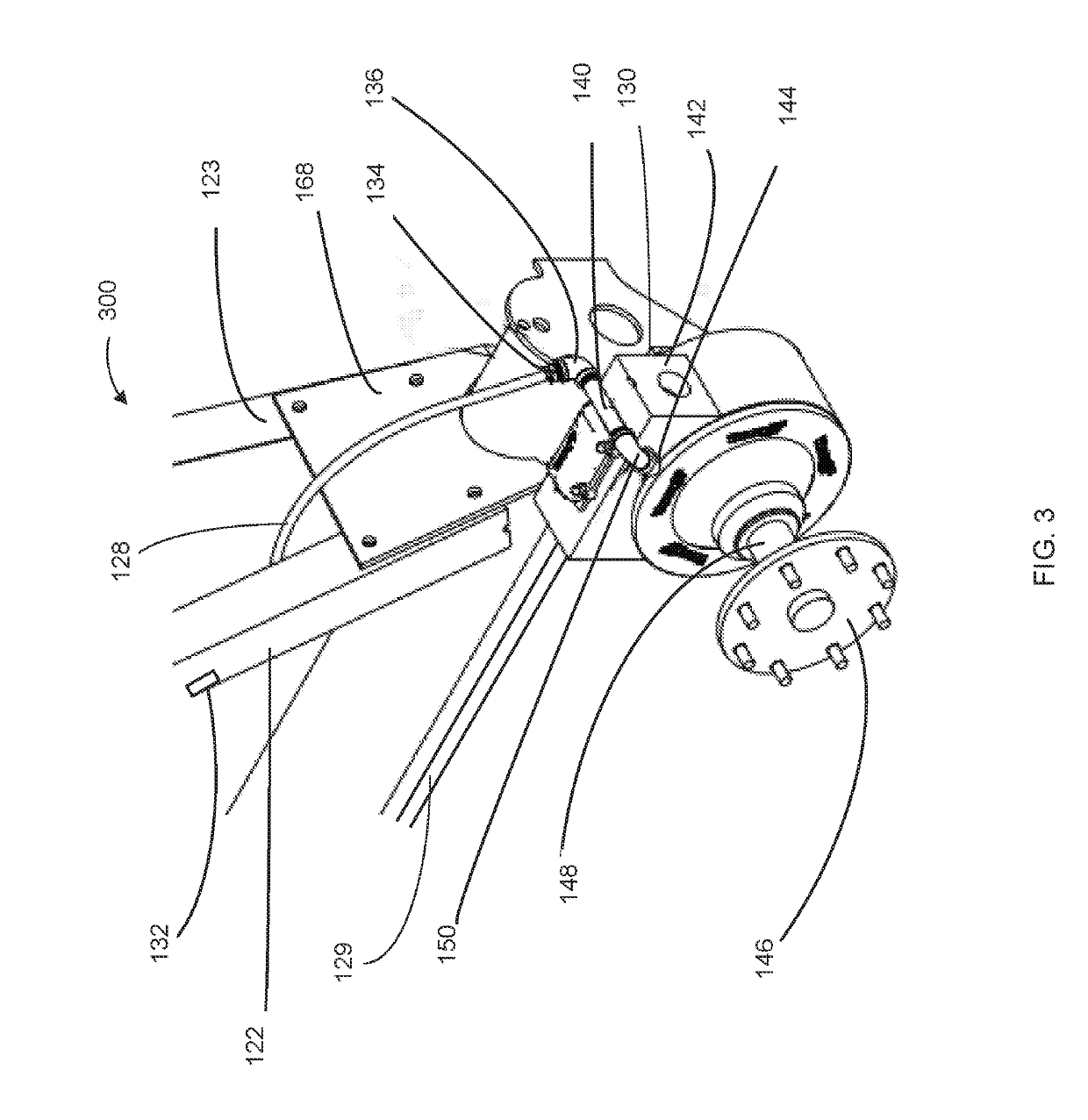
The present invention is a system for improving breathing in an irrigation machine. It includes a gearbox breather that is remotely mounted from the machine's location where mud and other debris are present. The gearbox breather system has a gearbox fill port and a breather line that connects to the gearbox using a connection assembly. The connection assembly includes a first elbow, a first pipe extension, and a hose barb. The gearbox also has a breather outlet that is connected to the angle mount on the first supporting leg using a breather connection assembly. This includes a third elbow, a fourth elbow, and a hose barb. Overall, this system helps to prevent the accumulation of mud and debris in the gearbox, improves breathing, and increases efficiency of the irrigation machine.

Problems solved by technology

To function properly, it is important for the gearbox to maintain a steady internal pressure at all times. However, with the rough operating conditions experienced by wheel tower gearboxes, a steady internal pressure is difficult to maintain.
Currently available solutions have proven faulty and inadequate.
Previous attempts installed breathers directly into the fill port of the wheel gearbox, which caused oil leakage due to gearbox oil expansion as well as created an opportunity for dirt and water (mud) falling from the tire during movement of the irrigation tower to block the breather or even penetrate the breather barrier, allowing these contaminants to enter the gearbox.
For each system of the prior art, numerous limitations exist.
In particular, each solution of the prior art allows for both oil leakage and water intrusion.

Method used


Image

  • Remotely mounted gearbox breather for an irrigation machine
  • Remotely mounted gearbox breather for an irrigation machine
  • Remotely mounted gearbox breather for an irrigation machine

Examples


Embodiment Construction

[0016]Reference is now made in detail to the exemplary embodiments of the invention, examples of which are illustrated in the accompanying drawings. Wherever possible, the same reference numbers will be used throughout the drawings to refer to the same or like parts. The description, embodiments and figures are not to be taken as limiting the scope of the claims. It should also be understood that throughout this disclosure, unless logically required to be otherwise, where a process or method is shown or described, the steps of the method may be performed in any order, repetitively, iteratively or simultaneously. As used throughout this application, the word “may” is used in a permissive sense (i.e., meaning “having the potential to”), rather than the mandatory sense (i.e. meaning “must”).

[0017]Additionally, any examples or illustrations given herein are not to be regarded in any way as restrictions on, limits to, or express definitions of, any term or terms with which they are utili...


PUM


Abstract

The present invention provides a remotely mounted gearbox breather for an irrigation machine. According to a preferred embodiment, the system of the present invention may preferably include a gearbox having a gearbox fill port and a breather line which is attached at a first end to the gearbox at the gearbox fill port using a connection assembly and at a second end to the breather assembly. According to a further preferred embodiment, the connection assembly of the present invention may preferably include a first street elbow connected at a first side to the gearbox; a first pipe extension connected to the first elbow and a second elbow; and a hose barb connected to the first end of breather line.

Description

RELATED APPLICATIONS[0001]The present invention claims priority to U.S. Provisional Application No. 62 / 574,782 filed Oct. 20, 2017.BACKGROUND AND FIELD OF THE PRESENT INVENTIONField of the Present invention[0002]The present invention relates generally to irrigation machines and, more particularly, to a remotely mounted gearbox breather for an irrigation machine.Background of the Invention[0003]Modern field irrigation machines are combinations of drive systems and sprinkler systems. Generally, these systems are divided into two types depending on the type of travel they are designed to execute: center pivot and / or linear.[0004]Regardless of being center pivot or linear, common irrigation machines most often include an overhead sprinkler irrigation system consisting of several segments of pipe (usually galvanized steel or aluminum) joined together and supported by trusses, mounted on wheeled towers with sprinklers positioned along its length. These machines move in a circular pattern ...

Claims


Application Information

Patent Timeline
Patent Type & Authority Applications(United States)
IPC IPC(8): F16H57/027A01G25/09A01G25/16F16K24/04F16H57/029
CPCF16H57/027A01G25/09F16H2057/02034F16H2057/02056F16K24/04A01G25/092
Inventor DILLON, CORY J.
Owner VALMONT INDUSTIES INC
Learn More