
Stripper clip

Active Publication Date: 2019-04-18
SPEEDPIN LTD
View PDF10 Cites 1 Cited by
  • Summary
  • Abstract
  • Description
  • Claims
  • Application Information

AI Technical Summary

Benefits of technology

The present invention provides a reliable 2-board stripping machine that can be operated using a similar level of reliability as a 3-board stripping machine that includes a bottom stripper frame. The boards can be accommodated in conventional stripping machines without requiring any changes to the control of the machine. The invention allows for the use of cheaper stripper pins compared to the pins required for a bottom stripper frame. This results in lower costs and the ability to dispose of worn-out stripper pins. The only change required for the invention is the definition of suitable cavities or sockets in the die board to accommodate the stripper clips. This can be easily done when designing the die board and does not unduly increase machining time.

Problems solved by technology

Where the punching board punching members comprise pins and no bottom stripper frame is employed, a common problem is that waste pieces may not be cleanly or fully removed from a blank.
Such waste pieces are either carried away with the blank and so may require that a product be rejected or need to be reworked—or worse, a waste piece may become stuck within a die board aperture, so preventing subsequent blanks from being properly positioned within the stripping machine and so causing the stripping machine to break down.
While bottom stripper pins are effective—assembling, mounting and dismantling of the bottom stripping frame is expensive and time consuming.

Method used


Image

  • Stripper clip
  • Stripper clip
  • Stripper clip

Examples


Embodiment Construction

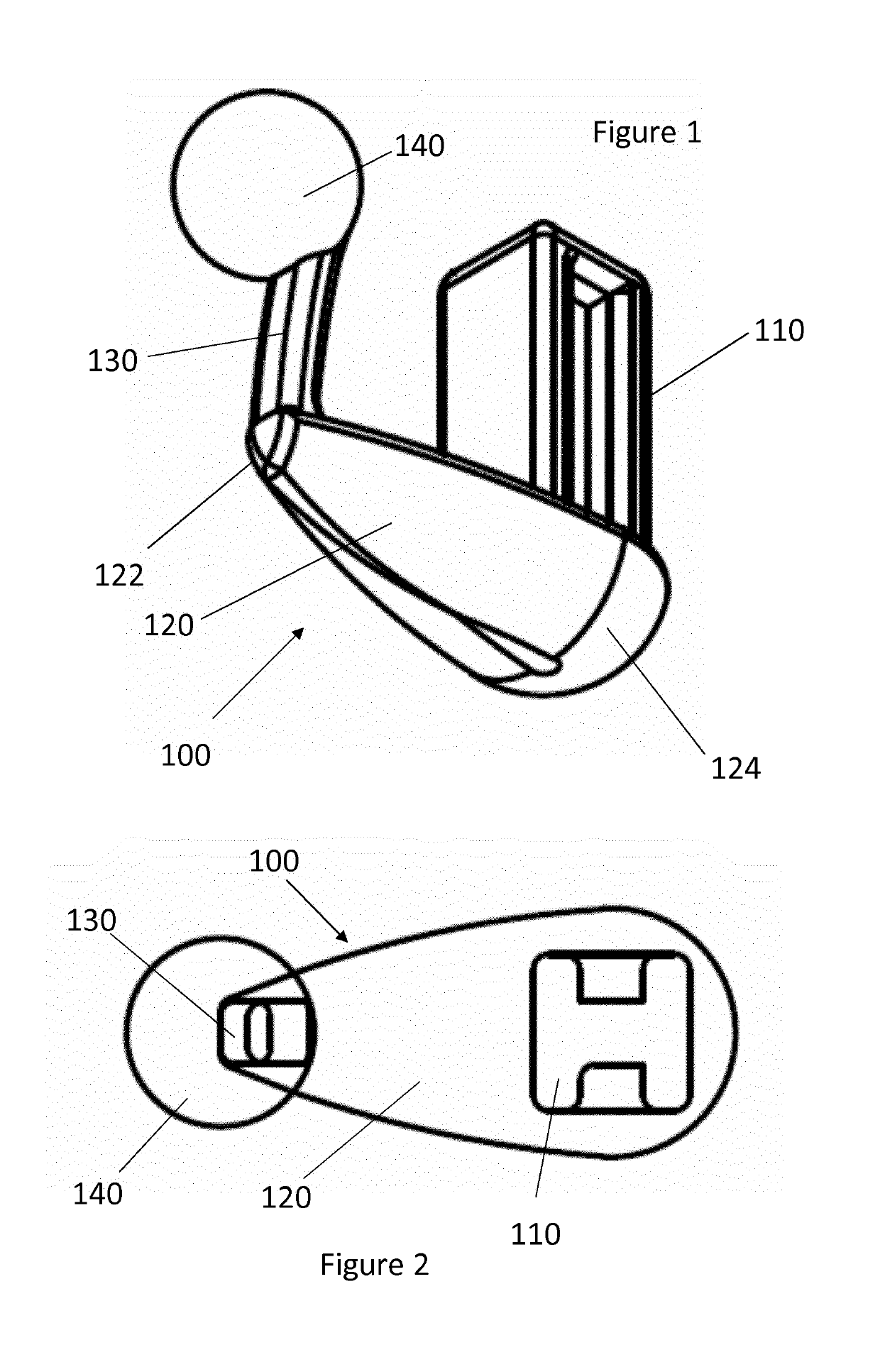
[0023]Referring now to FIG. 1 there is shown a stripper clip 100 according to an embodiment of the present invention. The clip 100 is integrally formed as a unitary piece of a stiff resilient material, preferably a plastics material. The clip 100 can be injection molded, machined or prototyped using a 3D printer. The stripper clip 100 may also be formed of metal or any other resilient material or a combination thereof such that stripper clip 100 is able to repeatedly recoil or spring back into shape after bending.

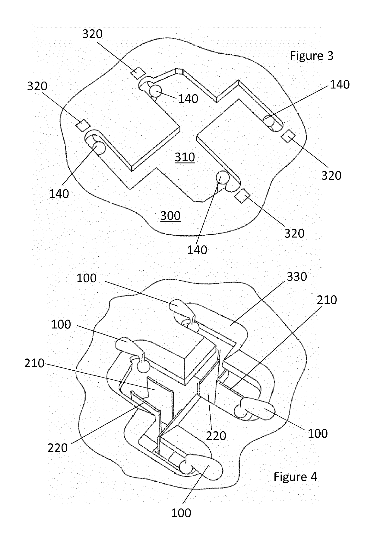
[0024]The stripper clip 100 has a hub 110 which is shaped to be inserted into a corresponding cavity or socket in a die board as explained in more detail below. In the embodiment, the hub 110 has a generally square outline, allowing it to be located in a socket with a pre-defined angular orientation—however, it will be appreciated that the hub can have a variety of shapes compatible with being inserted in a socket in a die board. Referring to FIG. 2, in the embodiment the h...


PUM


Abstract

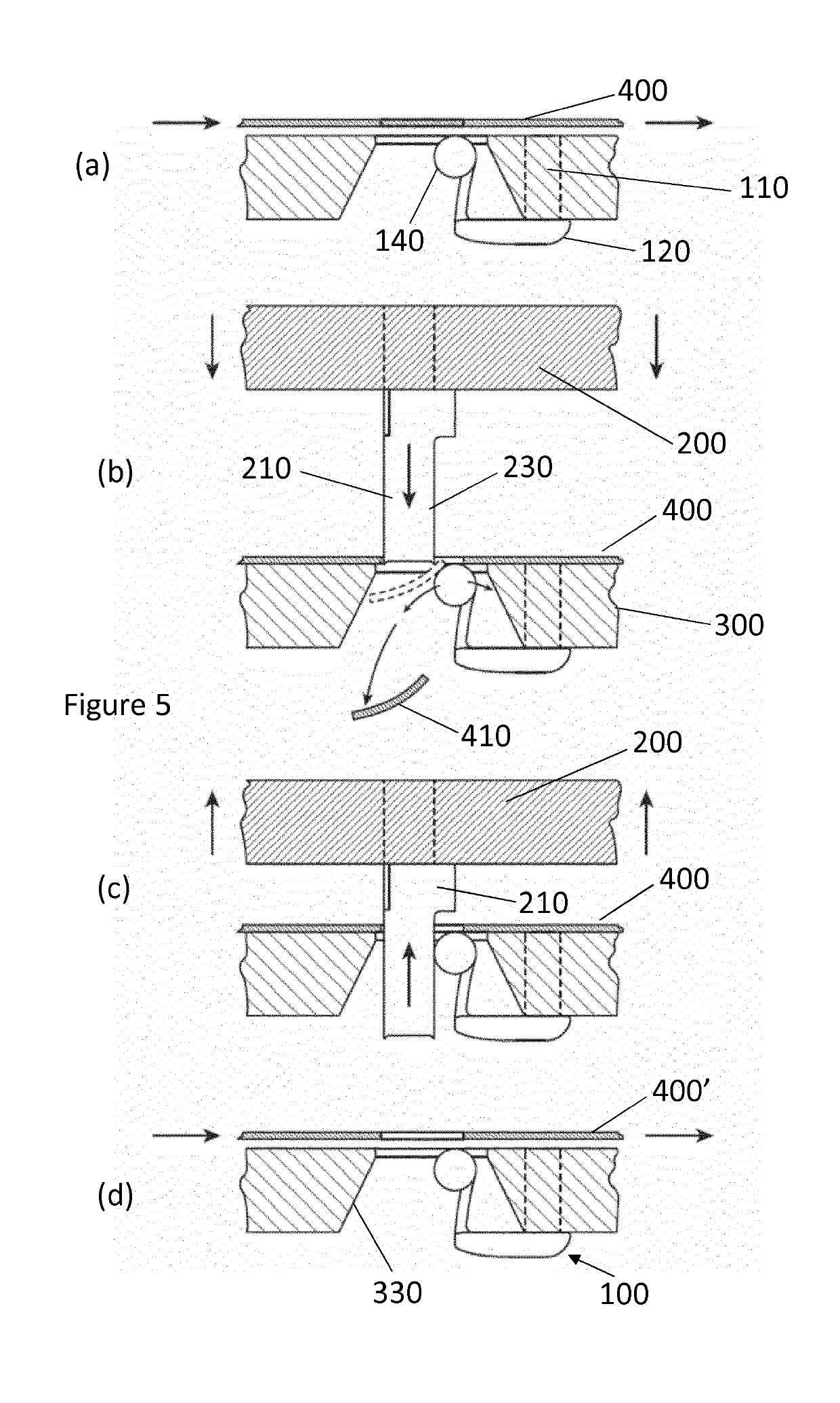
A stripper clip (100) for a die board (300) of a stripping machine, the stripper clip (100) comprising: a hub (110) to be fitted into a corresponding socket (320) of the die board (300); a bridge extending from the hub (110) to a distal end (122); and a cantilevered arm (130) extending from the distal end (122) of the bridge. The clip (100) is dimensioned to fit into a socket (320) of the die board (300) with the cantilevered arm (130) extending from an underside of the die board (300) into an aperture (310) of the die board (300) for receiving waste pieces from blanks. The clip (100) is formed of a resilient material so that the cantilevered arm (130) is deflected towards the hub (110) as a waste piece (410) passes through the die board (300) and so that the arm (130) reflexes as the waste piece (410) passes the cantilevered arm (130) to assist in disposing of the waste piece (410).

Description

FIELD OF THE INVENTION[0001]The present invention relates a stripper clip for use in stripping machines for producing card, paper or plastics blanks or the like.BACKGROUND TO THE INVENTION[0002]A variety of products are produced from card, paper or plastics blanks that are typically made from plain sheets which are cut and creased before being folded into shape.[0003]Typically, an outline for a product blank can be defined using, for example, a computer controlled laser or equivalent cutting device which can define outlines in either a single sheet or a stack of sheets. The outline can be defined as a line of weakening in which a number of frangible links (nicks) maintain the blank in position within the original sheet. When required, the blank can then be punched or stripped from the original sheet (or vice versa) leaving a peripheral piece of waste.[0004]It can also be desirable for a blank to include internal apertures requiring waste pieces to be removed from within the blank. A...

Claims


Application Information

Patent Timeline
IPC IPC(8): B26D7/18
CPCB26D7/18B26D2007/1809B26F2001/4445B26D7/1818
Inventor HIGGINS, MICHAEL
Owner SPEEDPIN LTD
Learn More