
Nerve locator

Active Publication Date: 2014-02-27
SKY MEDICAL TECH
View PDF1 Cites 1 Cited by
  • Summary
  • Abstract
  • Description
  • Claims
  • Application Information

AI Technical Summary

Benefits of technology

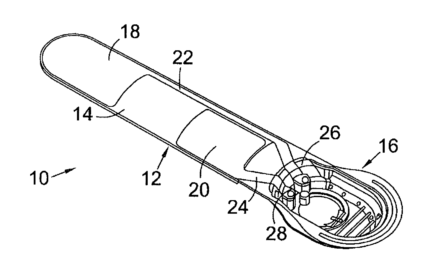
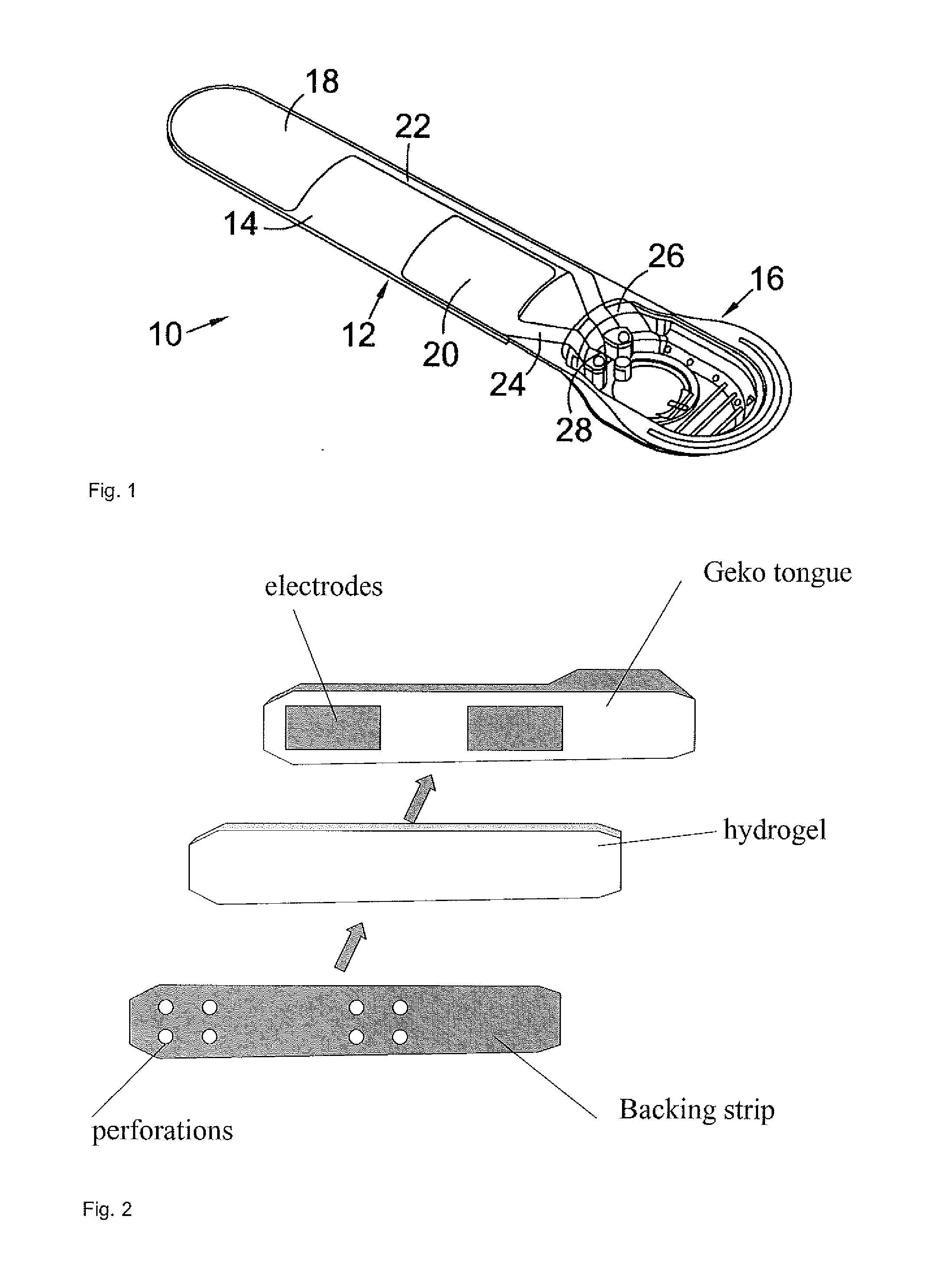
[0018]Preferably the cover comprises perforations which allow a portion of the conductive gel to be contacted through the cover. This provides a partially conductive cover by virtue of allowing electrical flow through the gel to the patient when the cover is in place. However, the use of perforations prevents most of the possible current flow. In this preferred embodiment it is possible that some portion of the conductive gel may be degraded during the location phase, but the majority of the gel will be protected by the cover. Furthermore, the use of a perforated cover provides ease of manufacture and use, since conventional materials (for example, plastics or papers) may be used to produce the cover, and creation of perforations is relatively straightforward. Note that in this em

Problems solved by technology

If the device is placed on the body incorrectly, then there may be reduced or even no stimulation of the correct nerve, such that the device will fail to operate as intended.
However there is of course some variation, and in some patients it may be more difficult to locate the correct position, or the correct position may differ more markedly from the norm.
Moving and repositioning the device (for example, to identify

Method used


Image

  • Nerve locator
  • Nerve locator
  • Nerve locator

Examples


Example

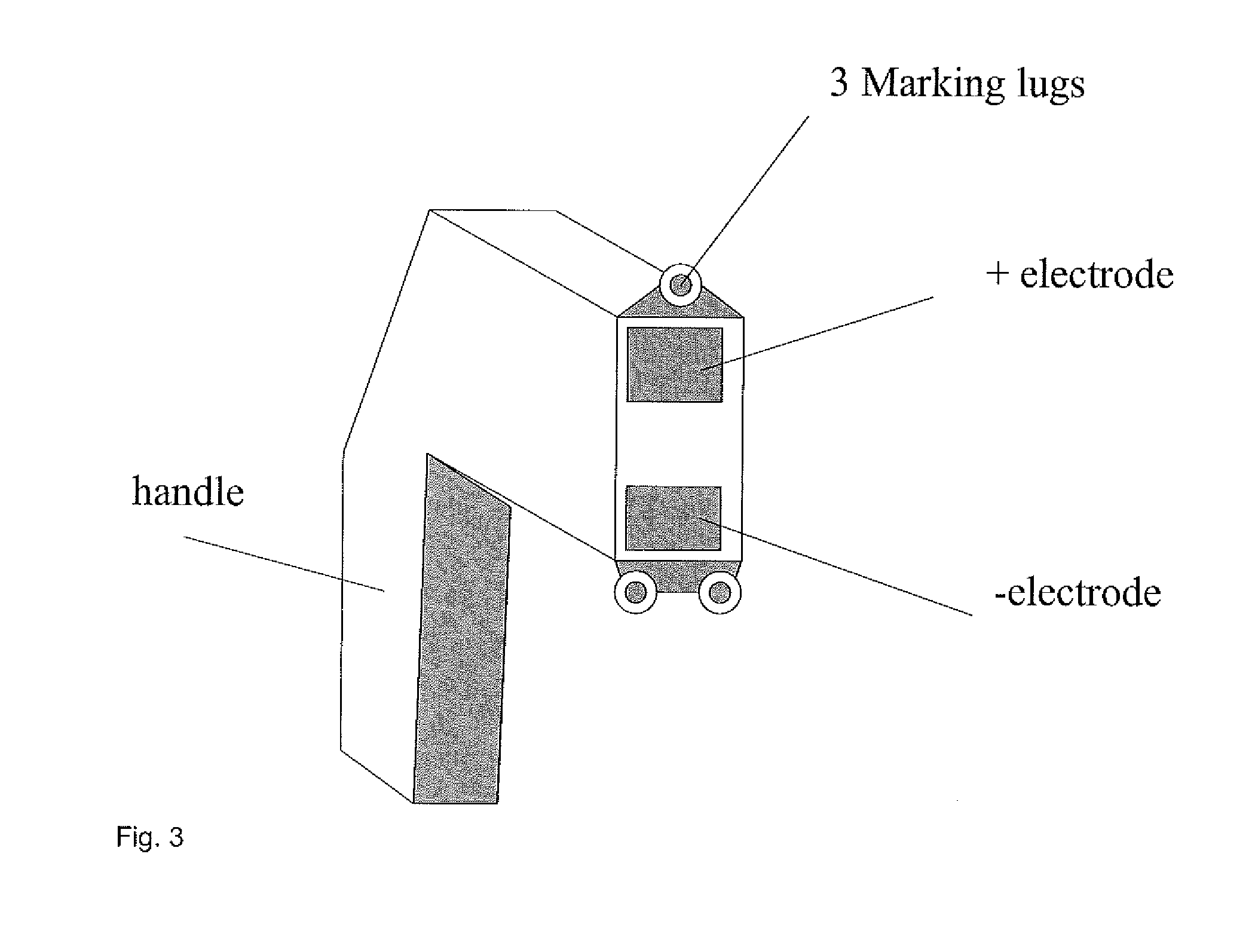
[0052]A second embodiment of a locator device is shown in FIG. 3. This takes the form of a rigid substrate having a handle, with a pair of electrodes being mounted on the substrate in the same configuration (that is, size, shape, and location) as the electrodes on the working electrical stimulation device. This locator device could be used to ‘scan’ the relevant region of the patient, having first prepared the skin with a suitable conductive aqueous or alcohol gel. Having found the correct location, this could then be marked using the marking lugs of the locator. For example, the locator may include a trigger which actuates the lugs to make a mark on the skin, or the locator may simply be pressed firmly against the skin such that the lugs make a temporary mark. After this the locator is removed, and a working stimulator device positioned in the correct location.


PUM


Abstract

A device for identifying appropriate nerve stimulation points on a patient is described, for use with an electrical stimulation device. In a first embodiment, the device includes electrodes located on a flexible substrate, a conductive gel layer overlying the electrodes, and a partially conductive removable cover overlying the gel layer. The device may be operated initially with the cover in place to allow reduced stimulation to identify a suitable nerve stimulation point. The cover may then be removed, and the device operated at the identified point. The cover may include perforations allowing the gel to contact the patient; or may be a sacrificial gel layer.

Description

FIELD OF THE INVENTION[0001]The present invention relates to a means whereby an appropriate stimulation point may be identified on a patient for use with transcutaneous electrical stimulation. Aspects of the invention relate to a modified device for electrical stimulation of a nerve of a patient, which device allows identification of an appropriate stimulation point and hence location of a nerve for such stimulation.BACKGROUND TO THE INVENTION[0002]Devices for transcutaneous electrical stimulation of nerves are described in international patent applications WO2006 / 054118 and WO2010 / 070332. The second of these describes a device including a flexible substrate on which are mounted positive and negative electrodes; a power supply connectable to the electrodes; and control means for activating the electrodes. The preferred embodiment of the device is in the form of an elongate “tongue” of flexible plastic which carries the electrodes (this is shown in FIG. 14 of WO2010 / 070332, reproduce...

Claims


Application Information

Patent Timeline
IPC IPC(8): A61B5/04
CPCA61B5/04001A61B5/05A61B5/4538A61B5/4887A61N1/3603A61N1/36031A61B5/24
Inventor TUCKER, ARTHURBAIN, DUNCAN
Owner SKY MEDICAL TECH
Learn More