
Traffic radar system with patrol vehicle speed detection

Active Publication Date: 2019-04-11
KUSTOM SIGNALS
View PDF0 Cites 1 Cited by
  • Summary
  • Abstract
  • Description
  • Claims
  • Application Information

AI Technical Summary

Benefits of technology

This patent describes a new traffic radar system that overcomes previous limitations. The system is made up of two radar transceivers, a speed-determining element, and a processing element. The first radar transceiver detects radar beams from the front of the patrol vehicle, while the second radar transceiver detects those from the rear of the vehicle. The speed-determining element identifies the speed of the patrol vehicle, and the processing element receives the digital data samples from the radar transceivers and converts them to determine the speed of target vehicles in front or behind the vehicle. This system can provide an accurate measure of vehicle speed, which can help improve safety on the road.

Problems solved by technology

But, connecting the traffic radar system to the patrol vehicle's speed detection electronics may be difficult and time consuming.

Method used


Image

  • Traffic radar system with patrol vehicle speed detection
  • Traffic radar system with patrol vehicle speed detection
  • Traffic radar system with patrol vehicle speed detection

Examples


Embodiment Construction

[0021]The following detailed description of the invention references the accompanying drawings that illustrate specific embodiments in which the invention can be practiced. The embodiments are intended to describe aspects of the invention in sufficient detail to enable those skilled in the art to practice the invention. Other embodiments can be utilized and changes can be made without departing from the scope of the present invention. The following detailed description is, therefore, not to be taken in a limiting sense. The scope of the present invention is defined only by the appended claims, along with the full scope of equivalents to which such claims are entitled.

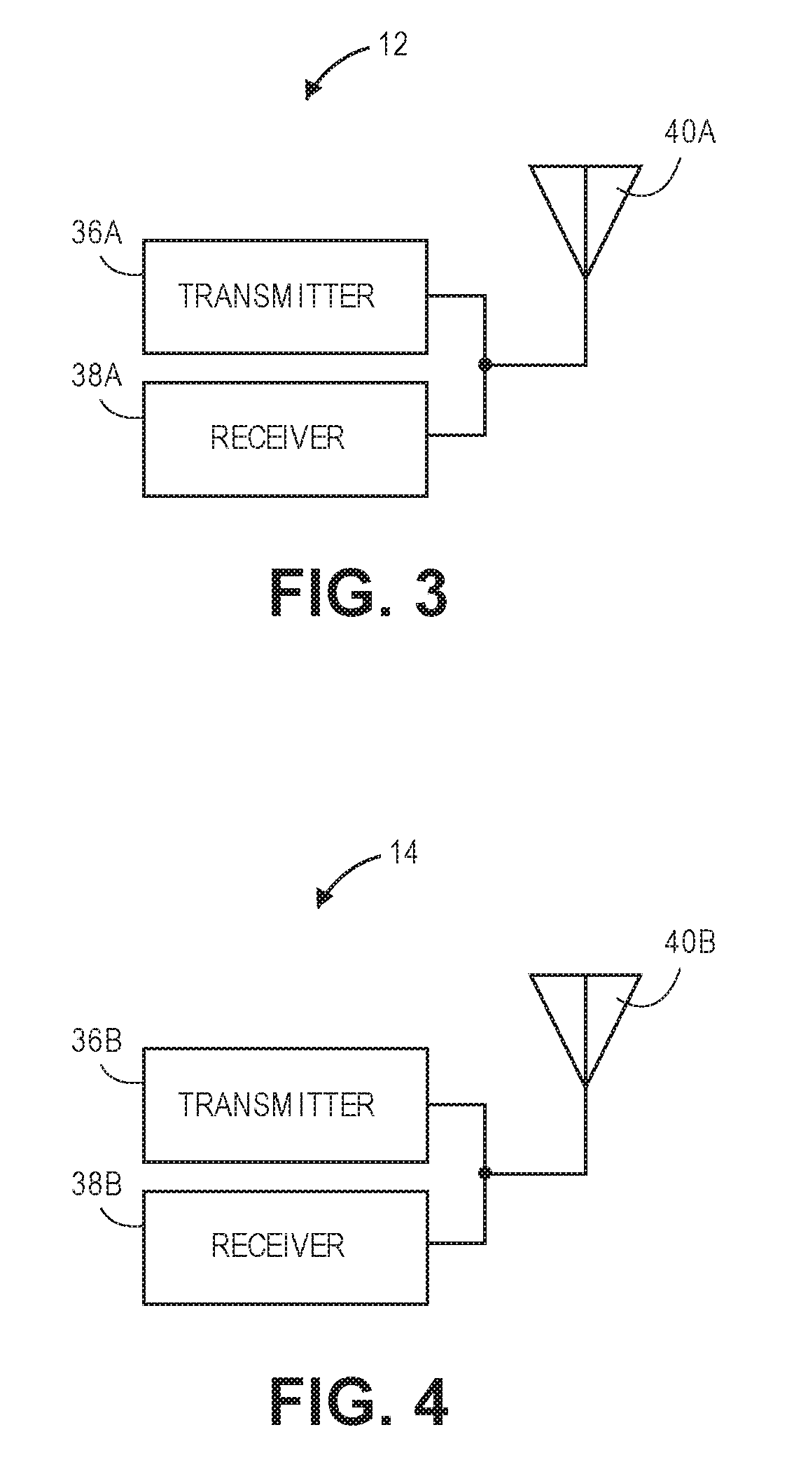
[0022]Referring to FIGS. 1 and 2, a traffic radar system 10, constructed in accordance with various embodiments of the current invention, broadly comprises a front radar transceiver 12, a rear radar transceiver 14, a display 16, a switch 18, an analog-to-digital converter (ADC) 20, a speed determining element 22, a memo...


PUM


Abstract

A traffic radar system comprises a first radar transceiver, a second radar transceiver, a speed determining element, and a processing element. The first radar transceiver transmits and receives radar beams and generates a first electronic signal corresponding to the received radar beam. The second radar transceiver transmits and receives radar beams and generates a second electronic signal corresponding to the received radar beam. The speed determining element determines and outputs a speed of the patrol vehicle. The processing element is configured to receive a plurality of digital data samples derived from the first or second electronic signals, receive the speed of the patrol vehicle, process the digital data samples to determine a relative speed of at least one target vehicle in the front zone or the rear zone, and convert the relative speed of the target vehicle to an absolute speed using the speed of the patrol vehicle.

Description

RELATED APPLICATIONS[0001]The current patent application is a non-provisional application which claims priority benefit to U.S. Provisional Application No. 62 / 569,667, entitled “TRAFFIC RADAR SYSTEM WITH MULTIPLE ZONE TARGET DETECTION”, and filed Oct. 9, 2017; U.S. Provisional Application No. 62 / 569,923, entitled “GPS ASSISTED PATROL SPEED SEARCH FOR DSP TRAFFIC RADAR”, and filed Oct. 9, 2017; and U.S. Provisional Application No. 62 / 570,446, entitled “TRAFFIC RADAR SYSTEM WITH ELECTRONIC TUNING FORK TEST FEATURE”, and filed Oct. 10, 2017. The earlier-filed provisional applications are hereby incorporated by reference in their entireties into the current application.BACKGROUND OF THE INVENTIONField of the Invention[0002]Embodiments of the current invention relate to radar systems that include patrol vehicle speed detectors to help determine target vehicle speeds.Description of the Related Art[0003]Traffic radio and ranging (radar) systems that are implemented in law enforcement patro...

Claims


Application Information

Patent Timeline
IPC IPC(8): G01S13/92G01S7/04
CPCG01S13/92G01S7/04G01S13/87G01S2013/932G01S7/2883G01S7/4082G01S7/4052G01S13/58G01S7/288
Inventor SHELTON, MAURICE
Owner KUSTOM SIGNALS
Learn More