
Method to produce a thermoplastic wear resistant foil

a technology of thermoplastic and wear resistance, applied in the direction of natural mineral layered products, synthetic resin layered products, flooring, etc., can solve the problems of inferior wear resistance of lvt floor panels, affecting the appearance of wear layers, and relatively easy wear of coatings and wear layers, etc., to achieve improved wear resistance, reduce the number of steps in the production process, and simplify the production process

Active Publication Date: 2019-03-28
VÄLINGE INNOVATION AB
View PDF4 Cites 28 Cited by
  • Summary
  • Abstract
  • Description
  • Claims
  • Application Information

AI Technical Summary

Benefits of technology

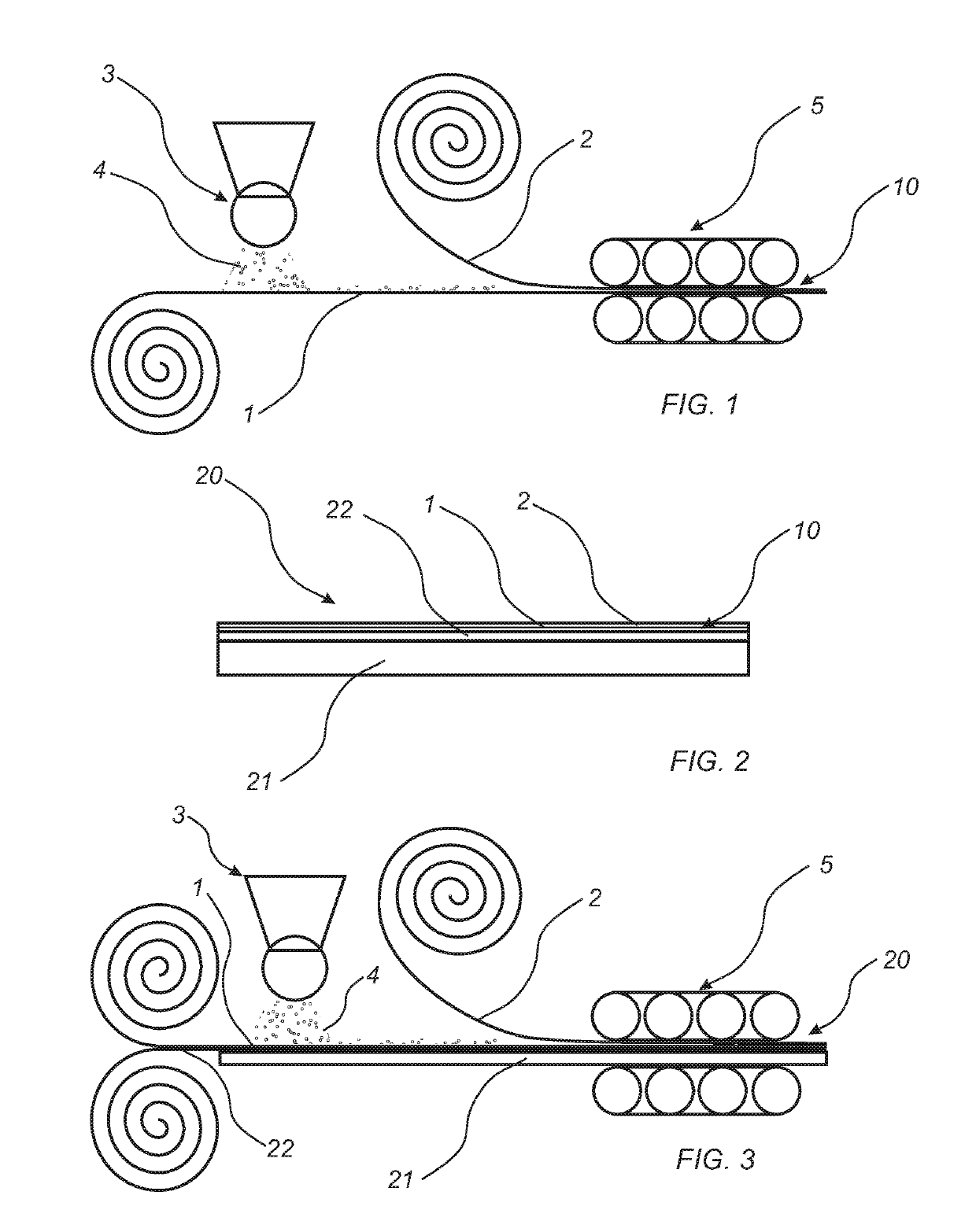
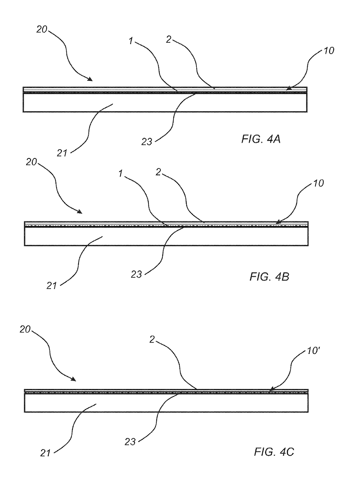
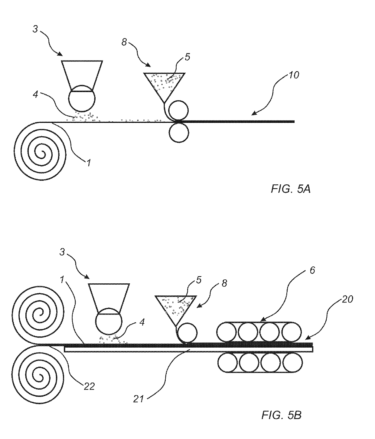
The present disclosure aims to improve the wear resistance of LVT floorings. By using a second thermoplastic material, namely polyurethane, in a layered structure, no additional coating with polyurethane is needed. This simplifies the production process and improves the chemical resistance of the wear resistant foil compared to conventional PVC coatings. Additionally, the upper layer of polyurethane provides improved resistance against black heel marks. The use of curable polyurethane also results in reduced shrinking during curing.

Problems solved by technology

However, when subjecting floor panels to wear, it has been shown that the coating and the wear layer are relatively easily worn down, or at least worn such that the appearance of the wear layer is affected, such as having scratches and / or not being transparent any longer.
Compared to a conventional laminate floor panel, the wear resistance of a LVT floor panel is inferior.
Usually, suitable thermoplastic material for the second foil may be more expensive compared to thermoplastic material used as, for example, in printed film or as core material.
If the wear resistant particles protrude beyond the surface of the second foil, the wear resistance foil will cause wear on items placed on the wear resistance foil.
For example, when the wear resistant foil is used as a top surface of a flooring, protruding wear resistant particles will cause wear on socks, shoes, etc.
Further, protruding wear resistant particles would cause a rough and / or harsh surface of the wear resistant foil, as provided by a slip resistant surface.

Method used


Image

  • Method to produce a thermoplastic wear resistant foil
  • Method to produce a thermoplastic wear resistant foil
  • Method to produce a thermoplastic wear resistant foil

Examples


example 1

ve Example

[0221]A PVC wear layer foil with a thickness of 0.3 mm was positioned on a decorative foil with a thickness of 0.1 mm. The two foils were laminated on to a PVC core material using a temperature of 160° C., a pressure of 20 bar and a pressing time of 40 seconds. The resulting product was a LVT product. The LVT product was found to have a wear resistance of 3200 revolutions as tested in a Taber abrader.

example 2

on PVC Foil

[0222]A PVC wear layer foil with a thickness of 0.3 mm was positioned on a decorative foil with a thickness of 0.1 mm. On to the wear layer foil 10 g / m2 Al2O3 was scattered using a scattering device. A second PVC wear layer foil with a thickness of 0.3 mm was positioned on the scattered Al2O3. The three foils were laminated on to a PVC core material using a temperature of 160° C., a pressure of 20 bar and a pressing time of 40 seconds. The resulting product was a LVT product. The LVT product was found to have a wear resistance higher than 8000 revolutions as tested in a Taber abrader.

example 3

n PVC Foil

[0223]A PVC wear layer foil with a thickness of 0.3 mm was positioned on a decorative foil with a thickness of 0.1 mm. On to the wear layer foil 10 g / m2 Al2O3 was scattered using a scattering device. A PU foil with a thickness of 0.05 mm was positioned on the scattered Al2O3. The three foils were laminated on to a PVC core material using a temperature of 140° C., a pressure of 20 bar and a pressing time of 40 seconds. The resulting product was a LVT product. The LVT product was found to have a wear resistance higher than 8000 revolutions as tested in a Taber abrader.


PUM

PropertyMeasurementUnit
refractive indexaaaaaaaaaa

Abstract

A method to produce a wear resistant foil, including providing a first foil including a first thermoplastic material, applying wear resistant particles on the first foil, applying a second foil including a second thermoplastic material on the first foil, and adhering the first foil and the second foil to each other to form a wear resistant foil.

Description

CROSS REFERENCE TO RELATED APPLICATIONS[0001]The present application is a continuation of U.S. application Ser. No. 14 / 790,774, filed on Jul. 2, 2015, which claims priority to Swedish Application Nos. 1550455-8, filed on Apr. 16, 2015, 1450895-6, filed on Jul. 16, 2014, and 1450894-9, filed on Jul. 16, 2014. The entire contents of each of U.S. application Ser. No. 14 / 790,774 and Swedish Application Nos. 1550455-8, 1450895-6, and 1450894-9 are hereby incorporated herein by reference in their entirety.FIELD OF THE DISCLOSURE[0002]The present disclosure relates to a method to produce a thermoplastic wear resistant foil, a method to produce a building panel including such a thermoplastic wear resistant foil, and a building panel.TECHNICAL BACKGROUND[0003]In recent years, so-called Luxury Vinyl Tiles and Planks (LVT) have gained increasing success. These types of floor panels usually comprise a thermoplastic core, a thermoplastic décor layer arranged on the core, a transparent wear layer...

Claims


Application Information

Patent Timeline
Patent Type & Authority Applications(United States)
IPC IPC(8): B32B27/08B32B27/36B32B27/14B32B27/20B32B27/30B32B27/32B32B27/40B32B5/18B32B37/24B29C48/15
CPCB32B27/36B29C48/15B32B27/20B32B27/304B32B27/08B32B27/32B32B2419/00B32B27/40B32B5/18B32B2307/584B32B2471/00B32B2317/16B32B2307/554B32B2250/24B32B37/24B32B2264/107B32B2264/067B29K2075/00B32B2419/04B32B2264/12B32B27/22B32B38/06B32B37/12B32B2264/02B32B33/00B32B2307/744B32B2264/101B29K2627/06B32B37/223B32B2250/246B32B27/065B32B37/1027B32B2250/40B32B2264/10B32B2309/105B32B38/145B32B2250/02B32B2307/412B32B2270/00B32B37/153B32B27/365B32B37/14B32B37/10B32B5/16B32B27/14B32B2264/102B32B19/045B32B19/048B32B21/02B32B21/08B32B21/12E04F15/105E04F15/107B32B27/302B32B27/308B32B37/156B32B37/185B32B37/04B32B7/06B32B2305/34B32B2607/00
Inventor LUNDBLAD, CHRISTERHAKANSSON, NICLASZIEGLER, GORAN
Owner VÄLINGE INNOVATION AB
Learn More