Smart air purification

a technology air speed, which is applied in lighting and heating apparatus, ventilation systems, heating types, etc., can solve the problems of unsatisfactory power consumption, large volume of air discharging apparatus, and high noise level, so as to reduce perceived draught, improve the pollutant removal efficiency of air purification apparatus, and reduce the effect of perceived draugh

Inactive Publication Date: 2019-03-28
KONINKLJIJKE PHILIPS NV
View PDF0 Cites 13 Cited by
  • Summary
  • Abstract
  • Description
  • Claims
  • Application Information

AI Technical Summary

Benefits of technology

[0008]The air purification apparatus according to embodiments of the present invention intelligently delivers purified air towards a target region, e.g. a region including a subject such as a person, based on the detection of pollutant levels in the air drawn from the target region. In this way, the subject in the target region may only be subjected to a directional air flow in the direction of the target region when the pollutant levels exceed a defined threshold, which improves the efficiency of the air purification apparatus and decreases the incidence of the perceived discomfort by the subject from the directional air flow.
[0018]In an embodiment, the air movement device comprises an electrode arrangement for generating an ionic wind, the electrode arrangement including opposing charging electrodes and a counter electrode arrangement in between the opposing charging electrodes. Such an air movement device has a particularly silent operation, which further reduces noise pollution by the air purification apparatus operating in the second configuration in particular.

Problems solved by technology

However, in order to maintain a healthy atmosphere in such enclosed environments, the air purification apparatus may have to displace relatively large volumes of air, in particular when the air purification apparatus has detected an elevated level of a pollutant of interest with an integrated pollutant sensor.
This operation is typically associated with elevated noise levels and noticeable air streams, i.e. wind, coming from the air purification apparatus, which may be perceived as unpleasant by the inhabitants of the enclosed environment in which the air purification apparatus is operational.
Moreover, the power consumption associated with such operation may be undesirable from an energy efficiency perspective.
However, such an air purification apparatus may still unnecessarily deliver air to the object.

Method used


Image

  • Smart air purification
  • Smart air purification
  • Smart air purification

Examples


Embodiment Construction

[0032]It should be understood that the Figures are merely schematic and are not drawn to scale. It should also be understood that the same reference numerals are used throughout the Figures to indicate the same or similar parts.

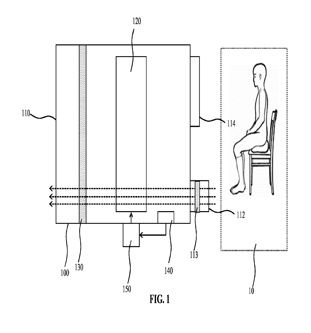
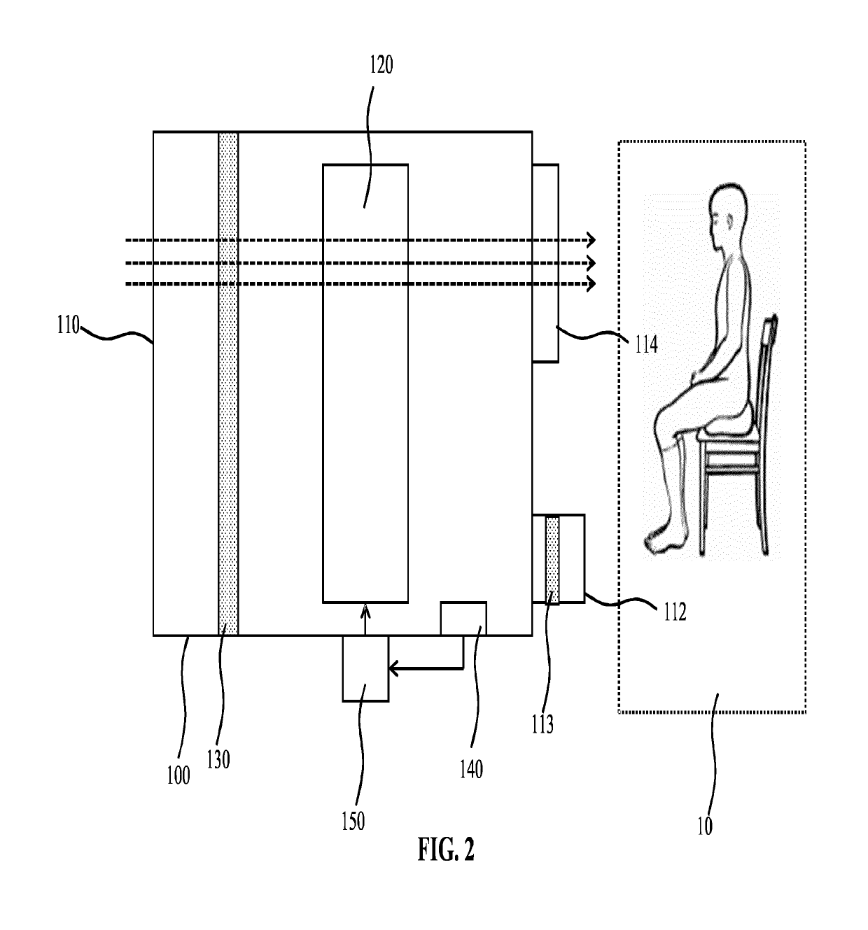
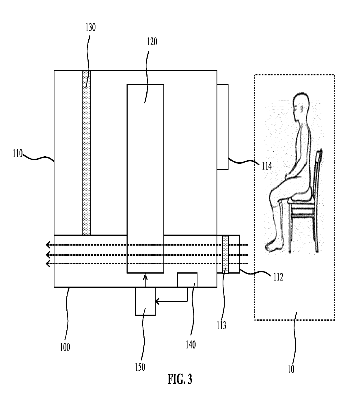
[0033]FIG. 1 schematically depicts an air purification apparatus 100 according to an embodiment in a first configuration and FIG. 2 schematically depicts the air purification apparatus 100 in a second configuration. The air purification apparatus 100 comprises a major vent 110 in fluid connection with a directional inlet 112 and a directional outlet 114 aimed at a region 10 of a target space such as a room, office space or the like housing the air purification apparatus 100. An air movement device 120 such as a fan, pump or the like fluidly connects the directional inlet 112 and the directional outlet 114 to the major vent 110. The major vent 110 preferably is arranged to displace air into or from a different region of the target space than the region 10. For...


PUM


Abstract

An air purification apparatus (100) for purifying air in a target space external to the apparatus is disclosed that comprises at least one pollutant removal structure (130; 131, 132) for removing a pollutant from the air in fluid connection with a major vent (110) and a directional vent arrangement comprising a directional inlet (112) for drawing air into the air purification apparatus from a region of the target space in an aiming direction of the directional inlet; and a directional outlet (114) for expelling air in a further aiming direction towards the region. An air movement device (120; 121, 122) configured to move air from the directional inlet to the major vent in a first configuration and to move air from the major vent to the directional outlet through the at least one pollutant removal structure in a second configuration responsive to a controller (150) is also present, as well as a sensor (140) arranged to determine a concentration of the pollutant in the air in said region when the air movement device is in the first orientation, wherein the controller is responsive to the sensor and is adapted to switch the air movement device from the first configuration to the second configuration upon the concentration of the pollutant exceeding a defined pollutant concentration threshold.

Description

FIELD OF THE INVENTION[0001]The present invention relates to an air purification apparatus for purifying air in a target space external to the apparatus, comprising at least one pollutant removal structure for removing a pollutant from the air and a directional vent arrangement.BACKGROUND OF THE INVENTION[0002]Air quality is a major concern in modern society. Increasing pollutant levels have been associated with a rise in respiratory conditions such as asthma and allergies. This has caused an increase in the desire to control the quality of air where possible, e.g. in enclosed environments such as rooms, office spaces and the like, to reduce the risk that the inhabitants of such enclosed environments are exposed to pollutant such as pollen particles, soot particles and so on, which may cause respiratory distress.[0003]This desire has led to an increased popularity in air purification apparatuses that can be deployed in such enclosed environments in order to capture potentially harmf...

Claims


Application Information

Patent Timeline
Patent Type & Authority Applications(United States)
IPC IPC(8): B03C3/36F24F7/007B03C3/12B03C3/41B03C3/47H01T23/00F24F7/003
CPCB03C3/368F24F7/007B03C3/12B03C3/41B03C3/47H01T23/00F24F2110/50F24F2110/60F24F2110/64F24F2110/66F24F2120/10B03C2201/24F24F2007/005B03C3/025B03C3/08F24F11/30Y02B30/70F24F11/38F24F7/003
Inventor HILBIG, RAINERKOERBER, ACHIM GERHARD ROLFBOUMA, PETER HERMANUSSU, JINGSHI, JUN
Owner KONINKLJIJKE PHILIPS NV
Why Eureka
Try Eureka