
Battery module

a battery module and battery technology, applied in the direction of secondary cells servicing/maintenance, cell components, association of printed circuit non-printed electric components, etc., can solve the problems of poor practicality and relatively high cost of battery modules, and achieve stable and effective fixing of battery modules, improve the reliability of fpc fixation, and improve the effect of stability

Inactive Publication Date: 2019-03-07
CONTEMPORARY AMPEREX TECH CO
View PDF2 Cites 4 Cited by
  • Summary
  • Abstract
  • Description
  • Claims
  • Application Information

AI Technical Summary

Benefits of technology

The present patent provides a battery module that can stably and efficiently fix the FPC, improves the fixation reliability of the FPC, facilitates the automatic production and reduces the cost. Compared with the fixing method of adhering the adhesive, the method for fixing the FPC in the battery module of the present disclosure has a wider applicable range, avoids the situations which are not beneficial to production, improves the production efficiency, and is beneficial to improve the production efficiency.

Problems solved by technology

Because of the structure and flexibility of the FPC itself, the FPC is usually fixed to the other components (such as batteries) of the battery module using a double-sided adhesive tape or a double-sided gum tape, but such a fixing method has the following two obvious defects: (1) the double-sided adhesive tape or the conventional double-sided gum tape has high requirements for the adhered surface, and the material of the adhered surface must adhere the adhesive of the double-sided adhesive tape or the adhesive of the conventional double-sided gum tape, for example, when the material of the components such as the battery is polypropylene (PP), the conventional double-sided gum tape cannot adhere to the surface of the components to form a stable adhesive layer, which cannot play a fixing role; (2) the double-sided adhesive tape or the double-sided gum take has a short service life, most of them cannot meet the service life requirement of the battery module, and even if some types of the double-sided adhesives can meet the service life requirement of the battery module, the cost of them will be relatively high and the practicality is not good.

Method used


Image

  • Battery module
  • Battery module
  • Battery module

Examples


Embodiment Construction

[0031]Hereinafter a battery module according to the present disclosure will be described in detail in combination with the figures.

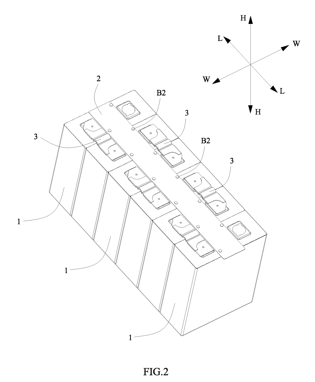
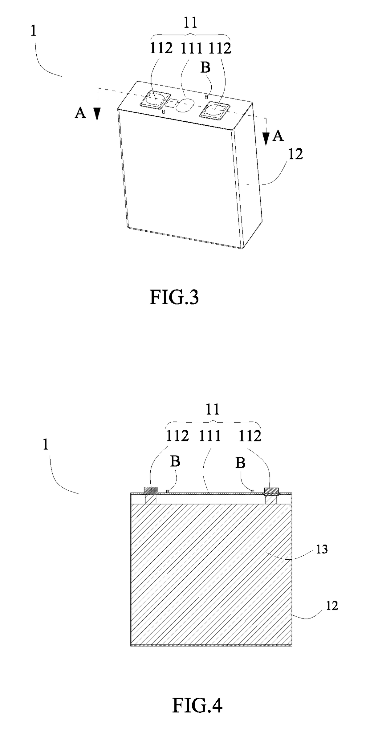
[0032]Referring to FIG. 1 to FIG. 9, a battery module according to the present disclosure comprises: a plurality of batteries 1 arranged side by side in a length direction L, each battery 1 includes a cap assembly 11, the cap assembly 11 includes a cap plate 111; and a FPC 2 positioned above the cap plates 111 of the plurality of batteries 1 in a height direction H. The cap plate 111 of at least one battery 1 is provided with a fixing column B, the FPC 2 is provided with a positioning hole 21 at a position corresponding to the fixing column B of the battery 1. The fixing column B has: a rod portion B1 received in the positioning hole 21 of the FPC 2, one end of the rod portion B1 is fixed to the cap plate 111; and a cover portion B2 connected with the other end of the rod portion B 1, covering the positioning hole 21 and fixed to the FPC 2.

[0033]In the b...


PUM

PropertyMeasurementUnit
lengthaaaaaaaaaa
heightaaaaaaaaaa
flexibleaaaaaaaaaa

Abstract

The present disclosure provides a battery module, which comprises: a plurality of batteries, each battery includes a cap assembly, the cap assembly includes a cap plate; and a FPC positioned above the cap plates of the plurality of batteries. The cap plate of at least one battery is provided with a fixing column, the FPC is provided with a positioning hole at a position corresponding to the fixing column. The fixing column has: a rod portion received in the positioning hole, one end of the rod portion is fixed to the cap plate; and a cover portion connected with the other end of the rod portion, covering the positioning hole and fixed to the FPC. The method for fixing the FPC of the battery module is stable and effective, improves the fixation reliability of the FPC, facilitates the automatic production and reduces the cost of the battery module.

Description

CROSS REFERENCE TO RELATED APPLICATIONS[0001]The present application claims priority to Chinese Patent Application No. CN201721139981.3, filed on Sep. 6, 2017, which is incorporated herein by reference in its entirety.FIELD OF THE PRESENT DISCLOSURE[0002]The present disclosure relates to the field of battery technology, and particularly relates to a battery module.BACKGROUND OF THE PRESENT DISCLOSURE[0003]At present, the use of a flexible printed circuit board (abbreviated as FPC) in the battery module is becoming more and more frequent, and using the FPC to collect low-voltage signals and temperature signals is a technique that has been promoting. Because of the structure and flexibility of the FPC itself, the FPC is usually fixed to the other components (such as batteries) of the battery module using a double-sided adhesive tape or a double-sided gum tape, but such a fixing method has the following two obvious defects: (1) the double-sided adhesive tape or the conventional double-...

Claims


Application Information

Patent Timeline
Patent Type & Authority Applications(United States)
IPC IPC(8): H01M10/42H01M10/48H01M2/20H01M2/04H05K3/36H05K1/18H01M50/147H01M50/209H01M50/262H01M50/284H01M50/287H01M50/505H01M50/509H01M50/51H01M50/512
CPCH01M10/4257H01M10/482H01M2/206H01M2/043H05K3/361H05K1/189H01M10/0468H01M10/425Y02E60/10H01M50/204H01M50/287H01M50/147H01M50/51H01M50/505H01M50/209H01M50/284H01M50/509H01M50/512H01M50/262
Inventor LI, JIANWEIYANG, MINGPINGZHENG, SONGTAI
Owner CONTEMPORARY AMPEREX TECH CO
Learn More