Method of configuring a test device designed to test an electronic control unit, and a configuration system

a technology of electronic control unit and configuration system, which is applied in the field of development of control units, can solve the problems of time-consuming and complicated configuration of test device properties in certain application scenarios, non-intuitive and slow configuration, and complex development process of control unit, and achieve the effect of accelerating the process

Inactive Publication Date: 2019-02-28
DSPACE DIGITAL SIGNAL PROCESSING & CONTROL ENG
View PDF0 Cites 0 Cited by
  • Summary
  • Abstract
  • Description
  • Claims
  • Application Information

AI Technical Summary

Benefits of technology

The present invention provides a new configuration system for HIL and RCP simulations that simplifies and makes the configuration process flexible and intuitive. The system offers a user-friendly interface for configuring the testing device by functional panels that guide the process. The positioning of the functional panels allows for quick and easy adjustment between them. Codegen generation and compiling facilitate faster and more efficient transmission and configuration of the testing device. Additionally, the system allows users to assign a new functional category to a configuration item, which provides greater flexibility in activating configuration items with different functional panels.

Problems solved by technology

The development of control units has become a highly complex process.
The known configuration systems or configuration diagrams have the disadvantage that the configuration of the test device properties in certain application scenarios is time-consuming and complicated.
In particular, it is a disadvantage that the configuration systems have a very large number of configuration items at different locations within the configuration system, which need to be changed often, resulting in a non-intuitive and slow configuration.

Method used


Image

  • Method of configuring a test device designed to test an electronic control unit, and a configuration system
  • Method of configuring a test device designed to test an electronic control unit, and a configuration system
  • Method of configuring a test device designed to test an electronic control unit, and a configuration system

Examples


Embodiment Construction

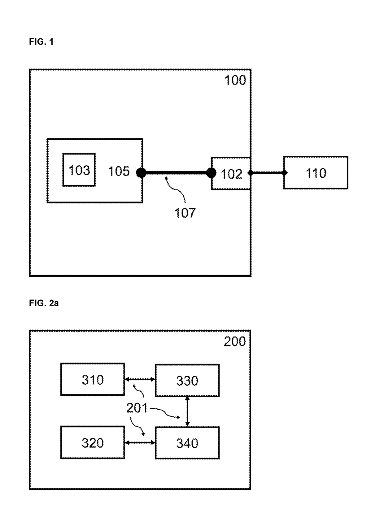
[0043]FIG. 1 shows a test device 100 on which a software model 103 of a technical system is executed on a calculation unit 105, wherein the software model or the calculation unit communicates via an input / output interface 102 of the test device, and an internal data connection 107 communicates with a device 110 connected to the test device. A calculation unit may be, e.g., a processor, an FPGA or an embedded PC. The communication with the test device can take place via the transmission of analog or digital electrical signals. The test device may include various hardware units (e.g., riser cards) that form the input / output interface 102. The input-output interface and the calculation unit 105 form a coherent system, but can also be spatially separated from each other and connected to each other via electronic connections.

[0044]For example, the test device 100 may be a hardware-in-the-loop (HIL) simulator. The test device 100 may also be a “Rapid Control Prototyping” (RCP) system. The...


PUM


Abstract

A configuration system of a test device designed for testing an electronic control unit. The test device is a hardware-in-the-loop simulator or a rapid control prototyping simulator. A software model of a technical system is executed on the test device and the software model communicates via an input / output interface of the test device with a device connected to the test device. Data is electronically transmitted by the communication, wherein the configuration system has a plurality of configuration items. The configuration items are assigned technical functional properties of the test device and the test device and / or the communication between the connected device and the software model is configured using the technical functional properties. The configuration items are assigned a functional category and are structured in functional panels in the configuration system.

Description

[0001]This nonprovisional application claims priority under 35 U.S.C. § 119(a) to German Patent Application No. DE10 2017 120 013.4, which was filed in Germany on Aug. 31, 2018, and which is herein incorporated by reference.BACKGROUND OF THE INVENTIONField of the Invention[0002]The present invention relates to the development of control units, as are used e.g., in the automotive industry or in the aerospace industry for the control of technical systems, such as motors or brakes. In particular, the present invention relates to test devices used in the development process of the control unit.Description of the Background Art[0003]The development of control units has become a highly complex process. Thus, new control units or new control functions should be tested as early as possible in the development process to check general functionality and to specify the further direction of development. Towards the end of the development process, it is important to test the already well-develope...

Claims


Application Information

Patent Timeline
Patent Type & Authority Applications(United States)
IPC IPC(8): G06F17/50
CPCG06F17/5009G06F30/20G06F2117/08
Inventor KRONMUELLER, MARTIN
Owner DSPACE DIGITAL SIGNAL PROCESSING & CONTROL ENG
Why Eureka
Try Eureka