Zoom lens and imaging apparatus

Active Publication Date: 2019-02-28
FUJIFILM CORP
View PDF0 Cites 2 Cited by
  • Summary
  • Abstract
  • Description
  • Claims
  • Application Information

AI Technical Summary

Benefits of technology

The present invention is aimed at providing a zoom lens that has good performance at a reduced size and weight with various aberrations satisfactorily corrected, especially chromatic aberration, while maintaining a high zoom ratio. The invention proposes a five-group configuration with appropriately set refractive power, position of the stop, and behavior of each lens group and stop during zooming, while satisfying predetermined conditional expressions. An imaging apparatus comprising the zoom lens is also provided.

Problems solved by technology

However, in the zoom lens of the above type, the lens group closest to the object side tends to become large and heavy in a case of increasing the zoom ratio.
Thus, there is a problem in that weight reduction is not easy or the zoom ratio thereof is lower than a zoom ratio necessary for the recent demands In addition, the zoom lens described in JP2015-94866A also has a problem that the zoom ratio is lower than a zoom ratio necessary for the recent demands

Method used


Image

  • Zoom lens and imaging apparatus
  • Zoom lens and imaging apparatus
  • Zoom lens and imaging apparatus

Examples


example 1

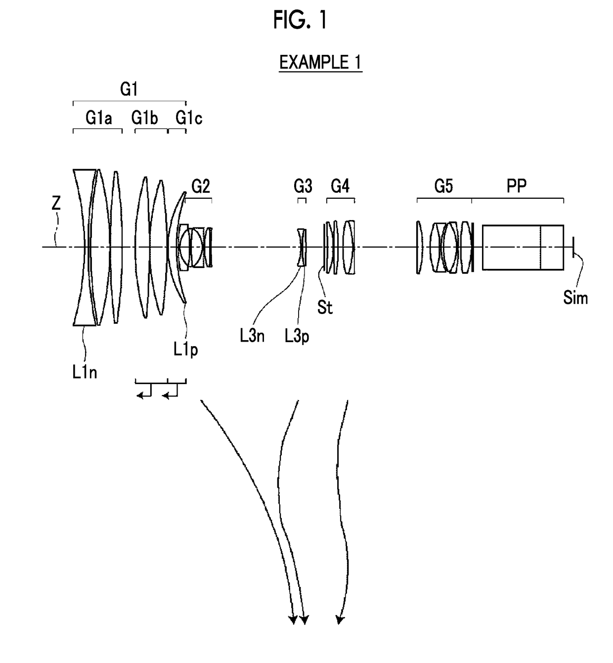
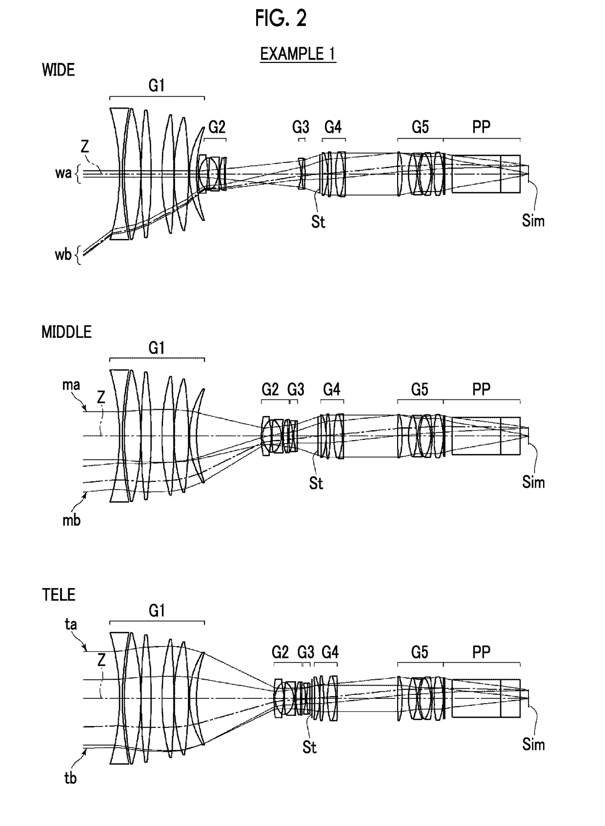
[0063]FIGS. 1 and 2 are cross-sectional views of a zoom lens of Example 1, and an illustration method thereof is as described above. Therefore, repeated description is partially omitted herein. The zoom lens of Example 1 consists of, in order from the object side to the image side, a first lens group G1 having a positive refractive power, a second lens group G2 having a negative refractive power, a third lens group G3 having a negative refractive power, an aperture stop St, a fourth lens group G4 having a positive refractive power, and a fifth lens group G5 having a positive refractive power. During zooming, the first lens group G1 and the fifth lens group G5 remain stationary with respect to the image plane Sim, the other lens groups move such that distances between lens groups adjacent to each other in the direction of the optical axis change, and the aperture stop St moves integrally with the fourth lens group G4. The first lens group G1 consists of, in order from the object side...

example 2

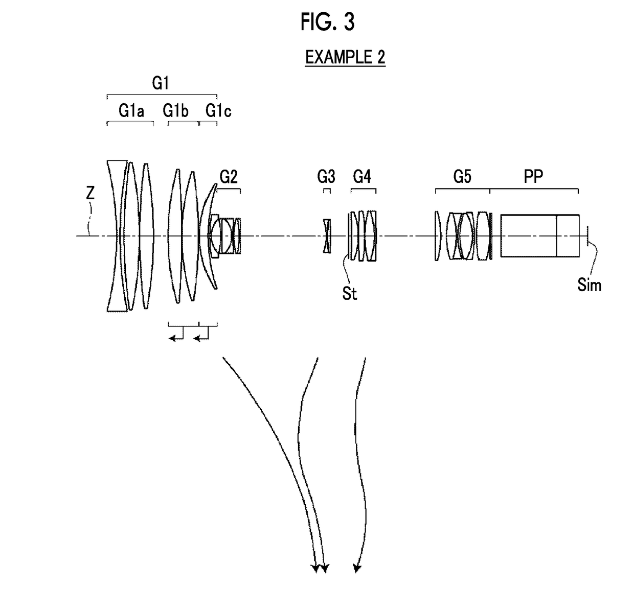
[0076]FIG. 3 is a cross-sectional view of a zoom lens of Example 2. The zoom lens of Example 2 has the same configuration as the outline of the zoom lens of Example 1. Table 4 shows basic lens data of the zoom lens of Example 2, Table 5 shows specification and variable surface distances, Table 6 shows aspheric surface coefficients, and FIG. 8 shows aberration diagrams in a state where the object at infinity is in focus.

TABLE 4Example 2SurfaceNumberRDNdνdθgF 1−174.78582.00001.8502632.350.59472 2227.30242.4601 3300.06799.09081.4338795.180.53733 4−212.93190.1200 5325.50498.16381.4370095.100.53364*6−220.62888.6400 7148.89078.11401.4338795.180.53733 8−476.77200.1200 9129.70699.69331.4370095.100.5336410−254.74770.60001158.34914.87171.7638548.490.558981294.5804DD[12]*13 76.04390.90002.0509026.940.605191414.61775.470315−46.84890.74501.8160046.620.5568216144.72096.00611.8589622.730.6284417−13.71560.73491.9537532.320.5901518290.50420.34261938.27543.01761.7847225.680.6162120−79.84570.74481.772...

example 3

[0077]FIG. 4 is a cross-sectional view of a zoom lens of Example 3. The zoom lens of Example 3 has the same configuration as the outline of the zoom lens of Example 1. Table 7 shows basic lens data of the zoom lens of Example 3, Table 8 shows specification and variable surface distances, Table 9 shows aspheric surface coefficients, and FIG. 9 shows aberration diagrams in a state where the object at infinity is in focus.

TABLE 7Example 3SurfaceNumberRDNdνdθgF 1−147.12362.00001.8061033.270.58845 2278.50482.1521 3387.42889.48801.4338795.180.53733 4−167.98110.1198 5554.36757.02911.4387594.660.53402*6−218.11457.2300 7155.42938.11721.4338795.180.53733 8−430.43860.1198 9128.88539.39861.4970081.540.5374810−298.33010.66001155.68365.12331.6956059.050.543481289.3508DD[12]*13 75.94430.90002.0010029.130.599521414.39916.083215−44.76520.74481.7725049.600.5521216284.34225.87251.8466623.780.6192317−14.46960.74041.9537532.320.5901518488.01630.17931937.14434.07391.7847225.680.6162120−46.76040.74561.788...


PUM


Abstract

The zoom lens consists of, in order from an object side, a first lens group having a positive power, a second lens group having a negative power, a third lens group having a negative power, a stop, a fourth lens group having a positive power, and a fifth lens group having a positive power. During zooming, the first lens group and the fifth lens group remain stationary, and the other lens groups and the stop move. The most image side positive lens is disposed to be closest to the image side in the first lens group. The following conditional expression relating to a partial dispersion ratio θgF1p of the most image side positive lens between the g line and the F line and an Abbe number ν1p is satisfied:0.6376<θgF1p+0.0017×ν1p<0.7.

Description

CROSS-REFERENCE TO RELATED APPLICATIONS[0001]The present application claims priority under 35 U.S.C. § 119 to Japanese Patent Application No. 2017-159235, filed on Aug. 22, 2017. The above application is hereby expressly incorporated by reference, in its entirety, into the present application.BACKGROUND OF THE INVENTION1. Field of the Invention[0002]The present invention relates to a zoom lens and an imaging apparatus, and more particularly to a zoom lens, which is suitable for a broadcast camera, a movie imaging camera, a digital camera, a video camera, a surveillance camera, and the like, and an imaging apparatus comprising the zoom lens.2. Description of the Related Art[0003]In the related art, a zoom lens having a four-group or five-group configuration has been used in a broadcast camera, a movie imaging camera, and a digital camera. For example, JP2015-152798A and JP2015-94866A disclose zoom lenses of a type which can be used in the above-mentioned camera and in which a lens gr...

Claims


Application Information

Patent Timeline
IPC IPC(8): G02B9/60G02B13/02G02B13/06G02B27/00
CPCG02B9/60G02B13/02G02B13/06G02B27/0037G02B15/17G02B15/14H04N5/262G02B15/145125H04N23/69G02B15/20G02B15/16G02B15/167G02B13/009G02B15/24G02B13/18G02B13/0045G02B5/005
Inventor SHIMADA, YASUTAKA
Owner FUJIFILM CORP
Why Eureka
Try Eureka