
Physical quantity sensor, method for manufacturing physical quantity sensor, complex sensor, inertia measurement unit, portable electronic apparatus, electronic apparatus, and vehicle

a manufacturing method and sensor technology, applied in the field of physical quantity sensors, can solve problems such as difficulty in providing physical quantity sensors, and achieve the effect of improving reliability and improving physical quantity detection sensitivity

Active Publication Date: 2019-02-28
SEIKO EPSON CORP
View PDF5 Cites 4 Cited by
  • Summary
  • Abstract
  • Description
  • Claims
  • Application Information

AI Technical Summary

Benefits of technology

This patent describes a physical quantity sensor with improved reliability and detection sensitivity. The sensor has a movable element with multiple openings that are located excluding the area where the movable element comes into contact with a protrusion on the support substrate. This improves the rigidity of the movable element and reduces damage from excessive acceleration. The sensor also has reduced damping, resulting in improved physical quantity detection sensitivity. Therefore, this patent provides a method for manufacturing the physical quantity sensor and an electronic apparatus or vehicle that includes the improved sensor.

Problems solved by technology

The physical quantity sensor described in U.S. Pat. No. 8,806,940, however, which is provided with openings over the entire surface of the movable element, has the following problem.
Thus, it is difficult to provide a physical quantity sensor having improved detection sensitivity and reliability.

Method used


Image

  • Physical quantity sensor, method for manufacturing physical quantity sensor, complex sensor, inertia measurement unit, portable electronic apparatus, electronic apparatus, and vehicle
  • Physical quantity sensor, method for manufacturing physical quantity sensor, complex sensor, inertia measurement unit, portable electronic apparatus, electronic apparatus, and vehicle
  • Physical quantity sensor, method for manufacturing physical quantity sensor, complex sensor, inertia measurement unit, portable electronic apparatus, electronic apparatus, and vehicle

Examples


embodiment

Configuration of Physical Quantity Sensor

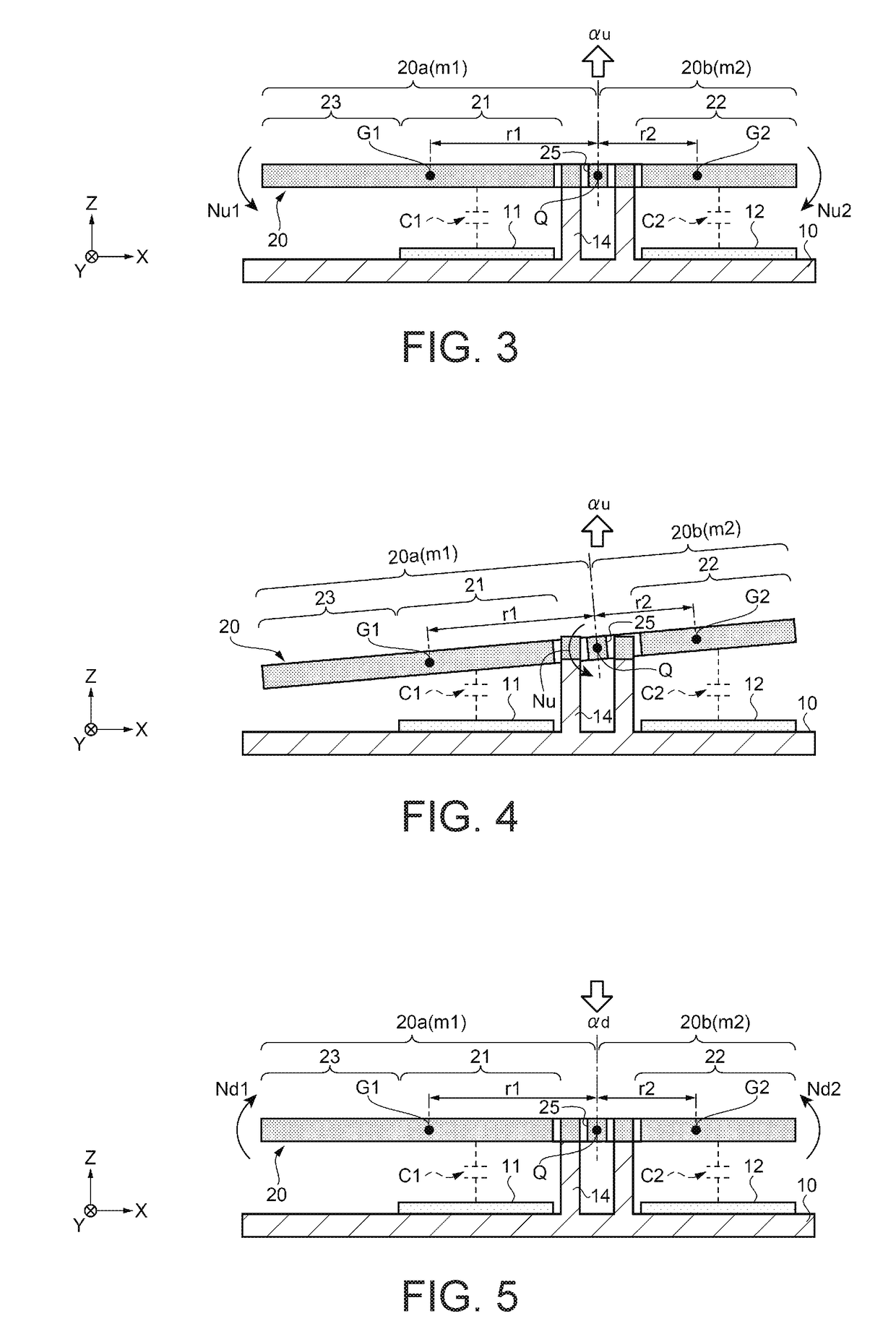
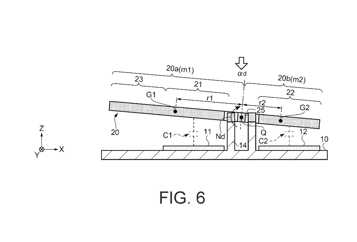
[0054]FIG. 1 is a plan view diagrammatically showing a physical quantity sensor according to an embodiment. FIG. 2 is a cross-sectional view taken along the line A-A in FIG. 1. A schematic configuration of a physical quantity sensor 100 according to the embodiment will first be described with reference to FIGS. 1 and 2. In FIG. 1, a lid 30 is omitted for ease of description.

[0055]The physical quantity sensor 100 according to the present embodiment can be used, for example, as an inertia sensor. Specifically, the physical quantity sensor 100 can be used, for example, as an acceleration sensor for measuring acceleration in the vertical direction (Z-axis direction) (capacitance-type acceleration sensor, capacitance-type MEMS acceleration sensor). In the present embodiment, it is assumed that the vertical direction is called the axis Z, the axial direction of the axis of rotation (beam 25), which will be described later, is called the axis Y, and...


PUM


Abstract

A physical quantity sensor includes a movable flat plate having a plurality of openings passing therethrough that is swingable around an axis of rotation, a support substrate linked to the flat plate via a column to suspend the movable flat plate over the support substrate via a gap, and a protrusion protruding toward the movable element. In a plan view, the openings are excluded from a D / 2-width annular range surrounding the outer circumference of the protrusion, where D is the maximum outer diametrical dimension of the protrusion.

Description

BACKGROUND1. Technical Field[0001]The present invention relates to a physical quantity sensor, a method for manufacturing the physical quantity sensor, a complex sensor, an inertia measurement unit, a portable electronic apparatus, an electronic apparatus, and a vehicle.2. Related Art[0002]A known physical quantity detector used to detect acceleration is configured in accordance with a rocker lever principle and detects acceleration acting in the vertical direction from capacitance that changes in accordance with the acceleration. For example, JP-A-2013-185959 discloses a physical quantity sensor formed of a movable element including a movable electrode section, a beam that supports the movable element, and a fixed electrode disposed on a substrate so as to face the movable electrode section. The physical quantity sensor needs to be configured to prevent the movable element from colliding with the substrate and breaking when an apparatus including the physical quantity sensor, for e...

Claims


Application Information

Patent Timeline
Patent Type & Authority Applications(United States)
IPC IPC(8): G01P15/08G01P15/125B81B5/00B81B3/00G01C19/5628
CPCG01P15/0802G01P15/125B81B5/00B81B3/0018G01C19/5628B81B2201/0235B81B2203/04G01C19/5656G01C19/5663G01P2015/0831G01P2015/0871
Inventor TANAKA, SATORU
Owner SEIKO EPSON CORP
Learn More