Stand Base with Rollers

a technology of standing base and rollers, which is applied in the direction of machine supports, braking systems, applications, etc., can solve the problems of requiring a substantial operating effort, requiring long, upward or laterally projecting levers and force transmission devices, and inconvenient operation of each roller or stand foot individually, so as to achieve easy and safe establishment and release, and high resistance to tilting

Active Publication Date: 2019-02-28
GLATZ AG
View PDF3 Cites 7 Cited by
  • Summary
  • Abstract
  • Description
  • Claims
  • Application Information

AI Technical Summary

Benefits of technology

The invention is a movable standing base for a vehicle that overcomes existing weaknesses. The base offers a stable situation without the need for raising the weight part and can be easily and safely established and released. The base has various configurational options including weight and design, and is accessible and walkable with an upper side. It is easy to operate, has a simple construction, is compact, non-slipping, and has a high resistance against tilting. The base allows for a easy and inexpensive construction, does not require any laborious pumping or cranking effort, and is readily recognizable as either in its movable or standingly stable state.

Problems solved by technology

This often requires long, upwardly or laterally projecting levers and force transmission devices.
This is disadvantageous because of the effort required, but also due to the presence of projecting parts such as levers.
Just these disadvantages, namely the necessity to raise the weight part of the standing base and thereby also to provide complicated operating elements extending to the outside of the standing base for just this lifting action, are also evident from DE 10 2014 006890 A1.
Moreover, in the case of the base disclosed in CN 105 249 638 A1, it is not a priori obvious whether the base is in the stable or in the rollable state, which is unsatisfactory for safety reasons.
The operation of each roller individually or each stand foot individually is inconvenient, confusing and requires a substantial operating effort and entails security risks.
Merging the various components of the stand foot with their respective lowering and reversing mechanisms onto a single central pumping pedal causes an undesirable manufacturing cost.

Method used


Image

  • Stand Base with Rollers
  • Stand Base with Rollers
  • Stand Base with Rollers

Examples


Embodiment Construction

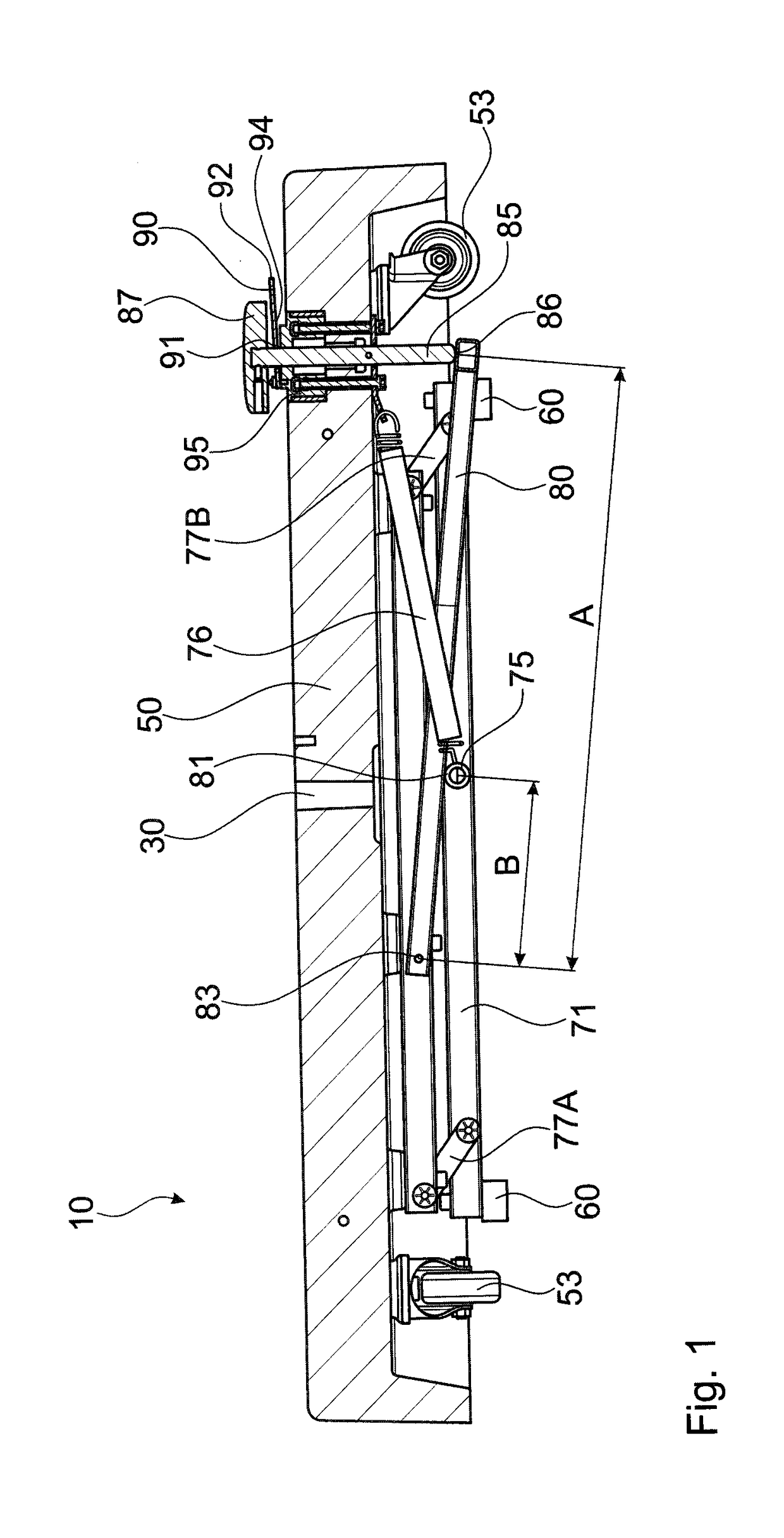
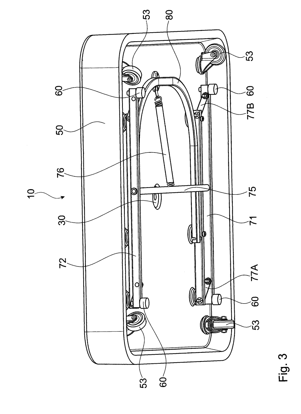
[0019]The movable standing base 10 with the stand tube 30 embedded in the base center as attachment elements for a parasol, a flag etc. shown in FIG. 1 comprises, in the present exemplary embodiment, a weight part 50, in the edge region of which four steering rollers 53 are firmly attached. At two bridge girders 71, 72, which in the exemplary embodiment are parallel and opposite to each other, and which are connected by means of a middle yoke 75 to form an H-shaped structure, four blocking feet 60 are arranged at respective edge regions of the bridge girders 71, 72. The bridge girders 71, 72 are each connected to the weight part 50 via parallel pivot levers 77A, 77B, 79A and 79.

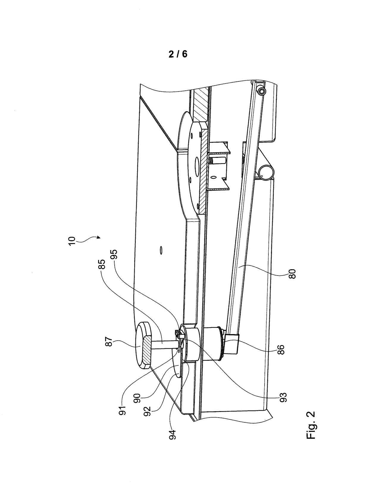
[0020]A tensioning lever 80, which in the exemplary embodiment is two-armed, is attached to the weight part 50, which tensioning lever is pivotable upwards and downwards at one end thereof. The tensioning lever rests on the middle yoke 75 and forms, with its other end, the connection to a pressure bolt 85, wh...


PUM


Abstract

A movable standing base for parasols, display boards, flagpoles and the like comprises a weight part having, firmly attached at the bottom side thereof, at least three, preferably four steering rollers, and it further comprises attachment elements for a parasol, for a display board, for a flagpole or for any other objects to be set up, and a plurality of preferably four lowerable blocking feet. In order to improve ease of handling without loss of stability, the blocking feet are connected to each other in the edge region of the weight part by two bridge girders arranged opposite to each other and a middle yoke and are anchored to the weight part in a substantially parallelogram shaped lowerable manner by two pivot levers. A tensioning lever is disposed resting on the middle yoke, and a pressure element leads to a blocking pedal at the upper side of the standing base.

Description

FIELD OF THE INVENTION[0001]The invention relates to a movable standing base for parasols, display boards, flagpoles or similar applications, the standing base comprising a weight part, rollers at the bottom side of the standing base and lowerable support feet to establish a standingly stable situation.BACKGROUND OF THE INVENTION[0002]There certainly exist some solutions as to how a movable standing base can be brought from a standingly stable situation on ground into a movable (rollable) situation and back again. In a plurality of solutions, it is proposed to raise the weight part so as to reach the movable (rollable) situation and to lower the weight part for reaching the standingly stable situation. This often requires long, upwardly or laterally projecting levers and force transmission devices. For an example, see EP 1 571 277 A1 (FIGS. 3a and 3b). This is disadvantageous because of the effort required, but also due to the presence of projecting parts such as levers.[0003]Just t...

Claims


Application Information

Patent Timeline
Patent Type & Authority Applications(United States)
IPC IPC(8): E04H12/22
CPCE04H12/2238F16M11/42F16M2200/08B60T1/14B60B33/0089A45B2023/0012
Inventor SIEGENTHALER, ROBERT ULRICH
Owner GLATZ AG
Why Eureka
Try Eureka