Control circuit and control method for wireless power transmission device
- Summary
- Abstract
- Description
- Claims
- Application Information
AI Technical Summary
Benefits of technology
Problems solved by technology
Method used
Image
Examples
first embodiment
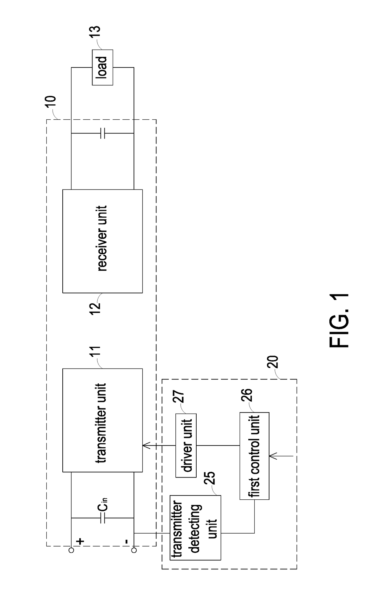
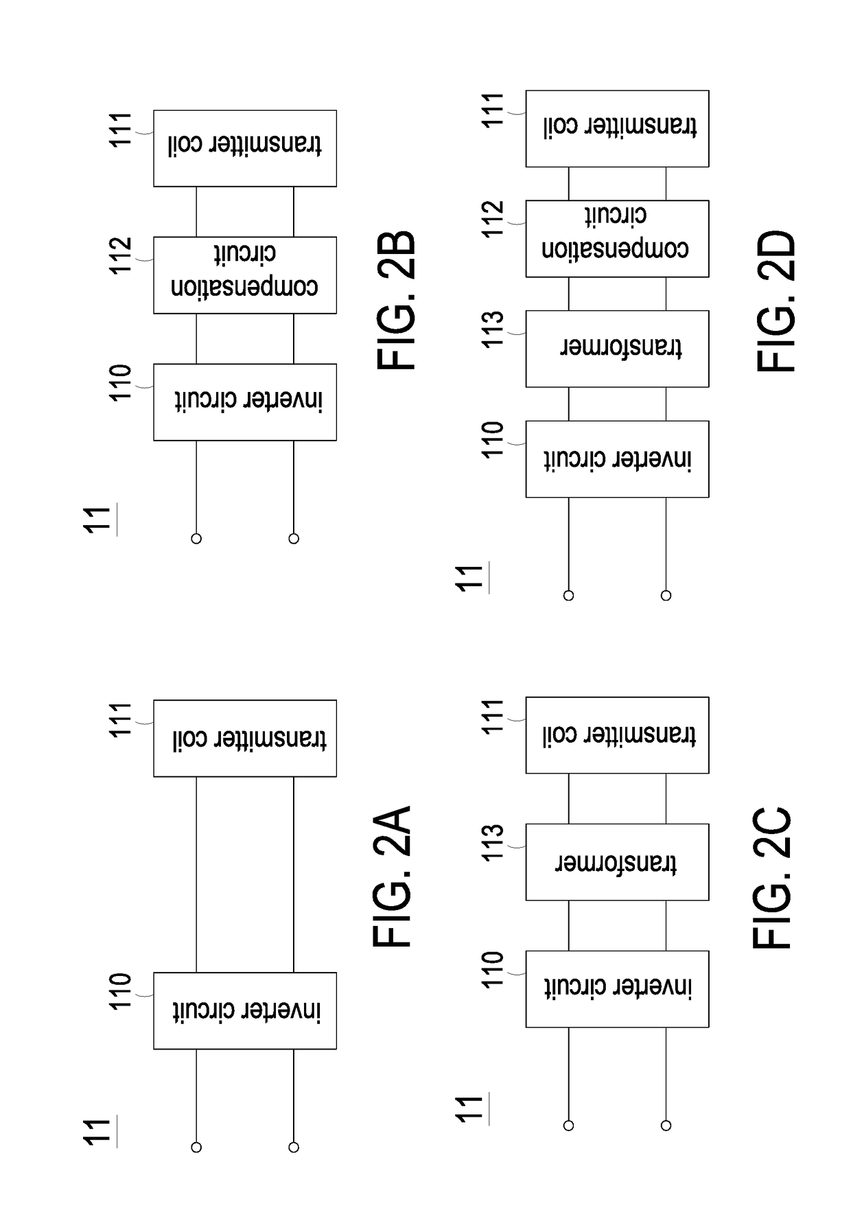
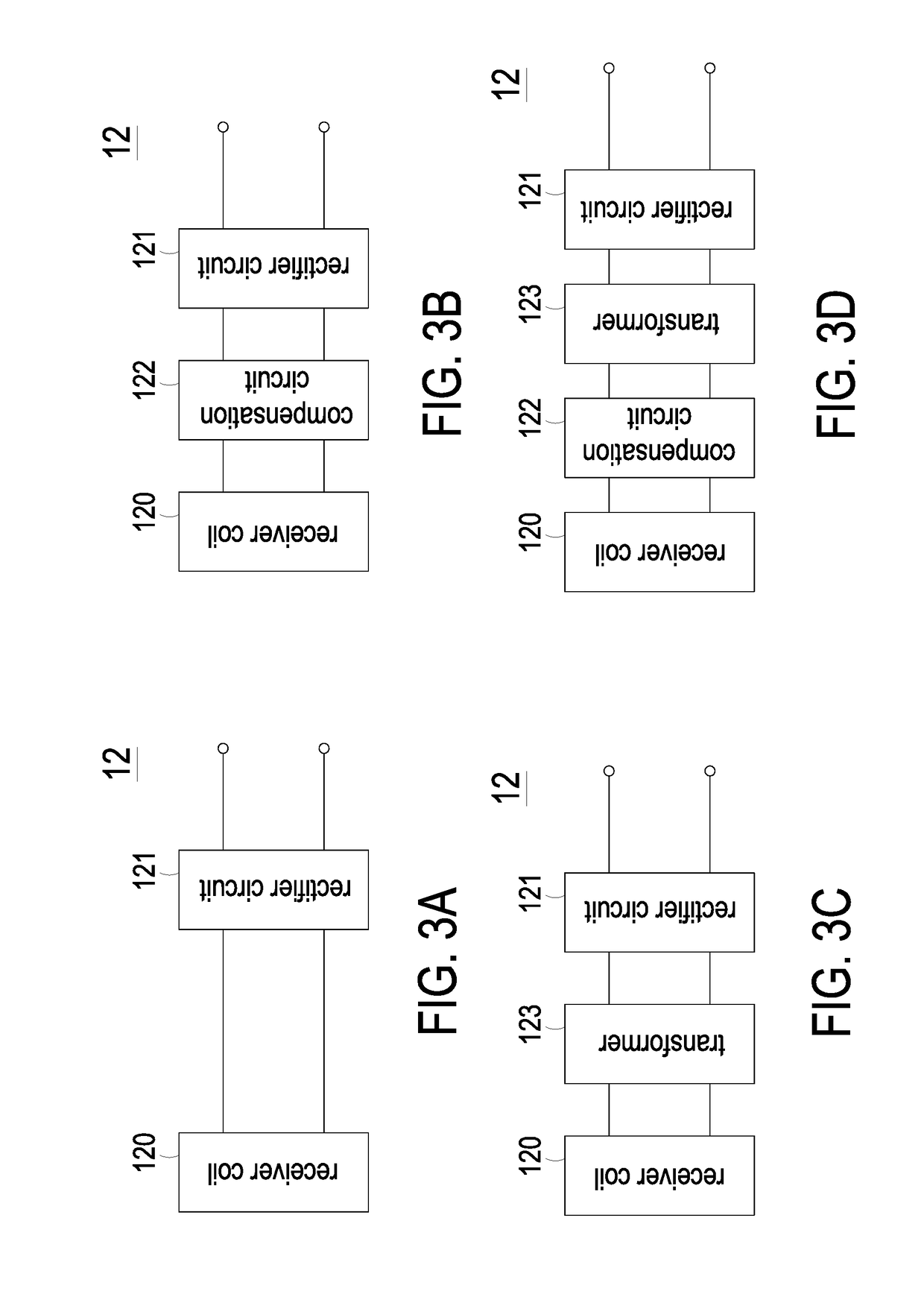
[0030]FIG. 1 is a schematic circuit diagram illustrating a wireless power transmission device and a control circuit for the wireless power transmission device according to the present disclosure. As shown in FIG. 1, the wireless power transmission device 10 comprises a transmitter unit 11 and a receiver unit 12. The transmitter unit 11 is used for receiving an input DC power and converting the input DC power into an AC power, and the AC power is transmitted from the transmitter unit 11. The receiver unit 12 receives the AC power from the transmitter unit through an electromagnetic coupling effect and converts the AC power into an output DC power so as to provide the electric power to a load 13. The control circuit 20 is used for controlling the wireless power transmission device 10. In this embodiment, the control circuit 20 comprises a transmitter detecting unit 25, a first control unit 26 and a driver unit 27.
[0031]The transmitter detecting unit 25 is electrically connected with i...
second embodiment
[0064]FIG. 9 is a flowchart illustrating a control method for a wireless power transmission device according to the present disclosure. The control method is applied to the wireless power transmission device of FIG. 6. The control method comprises the following steps.
[0065](a), the receiver detecting unit 21 detects the output of the receiver unit 12 and generates an output detecting signal (Step S901). (b), the first wireless communication unit 22 generates a wireless signal according to the output detecting signal (Step S902). (c), the second wireless communication unit 23 receives the wireless signal from the first wireless communication unit 22 and transforms the wireless signal to the output detecting signal (Step S903). (d), the second control unit 24 generates the reference input power signal according to a result of comparing the output detecting signal with the reference signal (Step S904). (e), the transmitter detecting unit 25 obtains an input power of the transmitter uni...
third embodiment
[0066]FIG. 10 is a flowchart illustrating a control method for a wireless power transmission device according to the present disclosure. The control method is applied to the wireless power transmission device of FIG. 7. The control method comprises the following steps.
[0067](a), the receiver detecting unit 21 detects the output of the receiver unit 12 and generates an output detecting signal (Step S1001). (b), the second control unit 24 generates the reference input power signal according to a result of comparing the output detecting signal with a reference signal Sref (Step S1002). (c), the first wireless communication unit 22 generates a wireless signal according to the reference input power signal (Step S1003). (d), the second wireless communication unit 23 receives the wireless signal from the first wireless communication unit 22, transforms the wireless signal to the reference input power signal, and transmits the reference input power signal to the first control unit 26 (Step ...
PUM
 Abstract
Description
Claims
Application Information
 - R&D
- Intellectual Property
- Life Sciences
- Materials
- Tech Scout
- Unparalleled Data Quality
- Higher Quality Content
- 60% Fewer Hallucinations
Browse by: Latest US Patents, China's latest patents, Technical Efficacy Thesaurus, Application Domain, Technology Topic, Popular Technical Reports.
© 2025 PatSnap. All rights reserved.Legal|Privacy policy|Modern Slavery Act Transparency Statement|Sitemap|About US| Contact US: help@patsnap.com


