
A rotary damper with self-repairing against attenuation

a rotary damper and self-repairing technology, applied in the direction of dampers, liquid based dampers, springs/dampers, etc., can solve the problems of weakening the damping effect, increasing the oil passage speed, and increasing so as to prolong the service life of the rotary damper, reduce the damping oil flowing through the rotating shaft and the bottom of the housing, and reduce the effect of damping

Inactive Publication Date: 2019-01-24
WANG XIANGJI
View PDF2 Cites 0 Cited by
  • Summary
  • Abstract
  • Description
  • Claims
  • Application Information

AI Technical Summary

Benefits of technology

This patent describes a device that can self-repair and avoid losing its effectiveness over time due to wear and tear. It includes a housing, a rotating shaft, and blades that connect with the shaft. These blades have a special structure that increases the resistance to the shaft's movement, causing them to elastically deform and attach tightly to the housing's inner wall. This structure also increases the resistance to the damping oil, which is used to control the movement. Overall, this design ensures that the device can perform its duties effectively for a long time without needing frequent maintenance or adjustment.

Problems solved by technology

However, after much use, the oil passage would become larger and the oil passing speed would become faster because of the abrasion of the outer wall and the lower end surface of the fastener, thereby weakening the damping effect.
The present disclosure can self-repair the problem of damping attenuation caused by the oversize oil passage, and can prolong the service life of the rotary damper.

Method used


Image

  • A rotary damper with self-repairing against attenuation
  • A rotary damper with self-repairing against attenuation
  • A rotary damper with self-repairing against attenuation

Examples


Embodiment Construction

[0035]The present disclosure will be described in details by referring to accompanying figures and embodiments as following:

[0036]Aspects of the present disclosure include a rotary damper with self-repairing against attenuation characteristics, and a self-locking force, which can be formed when the rotary damper moves to a certain angle along a damping direction, as to compensate the greater gap caused by abrasion and to improve the stability of the soft close period.

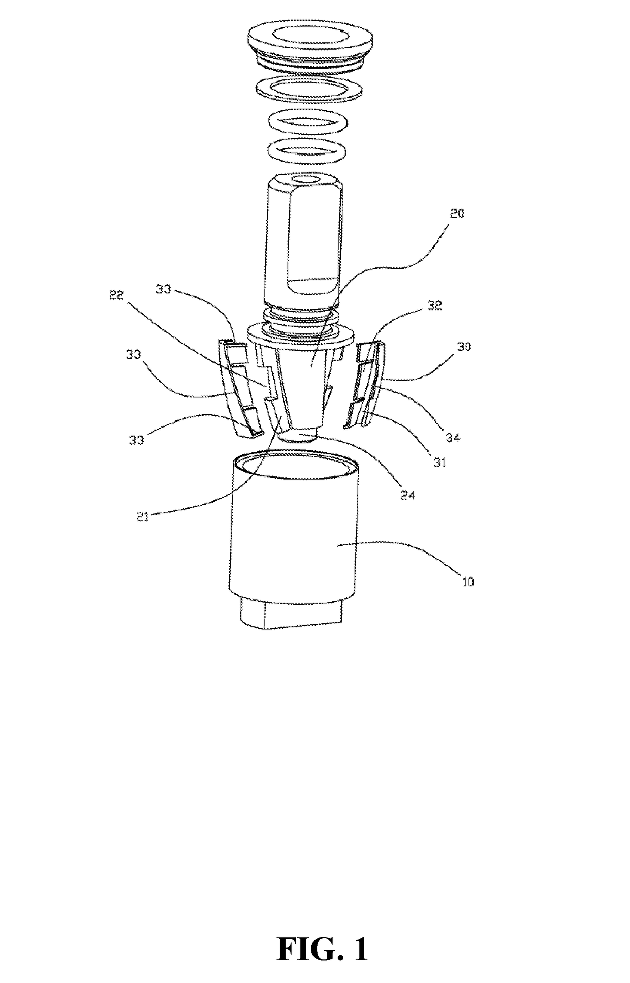
[0037]As shown in FIGS. 1 through 4, an embodiment of a damper comprises a housing 10, a rotating shaft 20, and a plurality of blades 30 connected with the rotating shaft 20. The blades 30 comprise a driving structure. When the rotating shaft 20 rotates towards a direction of damping formation, a driving force is applied on the drive structure by the damping oil, the blade 30 is driven by the drive structure, and the outer wall of the blade 30 is tightly attached to an inner wall of the housing 10. Thus, the gaps betwee...


PUM


Abstract

A rotary damper with self-repairing against attenuation, comprising a housing, a rotating shaft, and blades. The blades connect with the rotating shaft and comprise a driving structure. When the rotating shaft rotates towards a direction of forming damping, the driving force is applied on the drive structure by the damping oil. The blade is driven by the drive structure and elastically deforms the blades and extends outwardly to tightly attach to an inner wall of the housing. When the damping is formed, a downward pulling force is applied on the blades by the damping oil, and the blade drives the rotating shaft downward to tightly attach the bottom of the housing to generate a self-locking force. Furthermore, the damping oil flowing through the rotating shaft and the bottom of the housing can be reduced, to achieve a more stable damping effect.

Description

CROSS-REFERENCE TO RELATED APPLICATIONS[0001]The present application is a 35 U.S.C. § 371 National Phase conversion of International (PCT) Patent Application No. PCT / CN2017 / 071225 filed Jan. 16, 2017, which claims foreign priority of Chinese Patent Application No. 201610073233.3, filed on Feb. 2, 2016 in the State Intellectual Property Office of China, the contents of all of which are hereby incorporated by reference.TECHNICAL FIELD[0002]The present invention relates to a rotary damper, more particularly to a rotary damper with self-repairing against attenuation.BACKGROUND ART[0003]In the present technology, after a rotary damper has been used a certain number of times, the oil passage becomes larger and the soft closing period shorter with the wearing of accessories.[0004]The Chinese utility model patent application No. 201220364330.5 discloses a rotary damper comprising a housing with an opening on one end and a rotating shaft. A shaft core is formed on the bottom of the rotating ...

Claims


Application Information

Patent Timeline
Patent Type & Authority Applications(United States)
IPC IPC(8): F16F9/14F16F9/32A47K13/12
CPCF16F9/145F16F9/3207A47K13/12F16F2232/02F16F9/125F16C11/04F16F9/14
Inventor WANG, XIANGJICHEN, WENCHENG
Owner WANG XIANGJI
Learn More