
Conductive component structure for wire connection terminal

Active Publication Date: 2019-01-10
SWITCHLAB +1
View PDF6 Cites 3 Cited by
  • Summary
  • Abstract
  • Description
  • Claims
  • Application Information

AI Technical Summary

Benefits of technology

The present invention provides a conductive component structure for wire connection terminal with higher electro-conductive performance and more securely assembled with the conductive wire. The conductive component includes a main body in the form of a plate body and a restriction body connected on the main body. The restriction body has a base section, a bow section connected with the base section, and a free section connected with the bow section, which together provide elastic effect for the restriction body. When the conductive wire is plugged into the case into contact with the conductive component, the restriction body guides the conductive wire and ensures better stability and efficiency. The conductive component structure has improved shortcomings of conventional structures where the conductive wire is prone to deformation and unstable contact. The restriction body has an elastic body for elastically pressing and restricting the conductive wire to minimize the possibility of deformation. An arched depression and a retarding section is formed on the restriction body to prevent the conductive wire from rotating and ensuring stable assembly. The main body or the restriction body has a stop section to restrict the plug-in length or distance of the conductive wire. The conductive component structure provides better guidance for the conductive wire to pass through the mouth section into the conductive component to be securely pressed by the restriction body.

Problems solved by technology

Unless an operator uses a tool to extend into the case and push / press the metal leaf spring, the conductive wire cannot be released from the electrical connection or contact with the metal leaf spring and the conductive component.
For example, when a large-diameter conductive wire is plugged into the electrical connection terminal, it often takes place that the pressing force applied by the metal leaf spring and the conductive component to the conductive wire is insufficient so that the conductive wire can be hardly securely pressed and the conductive wire is apt to rotate, deflect or swing due to incautious touch of an operator.
This will lead to poor contact and insecurity.
However, as well known by those who are skilled in this field, it is quite troublesome and time-costing to use a screw to lock and restrict or release the conductive wire.
Also, the increase of the thickness of the metal leaf spring and the conductive component will lead to increase of the manufacturing cost and it is laborious to operate the thickened metal leaf spring and conductive component.
Also, the conductive component and / or the metal leaf spring of the electrical connection terminal must overcome the shortcomings of the conventional electrical connection terminal that the pressing force applied by the metal leaf spring and the conductive component to the conductive wire is insufficient, the conductive wire can be hardly securely pressed and the conductive wire is apt to deflect or swing due to incautious touch of an operator to lead to poor contact and insecurity.2. In addition, the conductive component and / or the metal leaf spring of the electrical connection terminal must be free from the screw of the conventional electrical connection terminal for locking and restricting the conductive wire and eliminate the shortcoming of the conventional electrical connection terminal that it is quite troublesome and time-costing to use the screw to lock and restrict or release the conductive wire.
Also, the conductive component and / or the metal leaf spring of the electrical connection terminal must improve the shortcoming of the conventional electrical connection terminal that the thickness of the metal leaf spring and the conductive component is increased to lead to increase of the manufacturing cost and it is laborious to operate the thickened metal leaf spring and conductive component.3. Moreover, the electrical connection terminal must provide a conductive component structure, which is able to help the metal leaf spring in pressing the conductive wire and is able to guide the conductive wire and help in fixing the conductive wire so as to minimize the possibility of rotation, deflection or swing of the conductive wire.

Method used


Image

  • Conductive component structure for wire connection terminal
  • Conductive component structure for wire connection terminal
  • Conductive component structure for wire connection terminal

Examples


Embodiment Construction

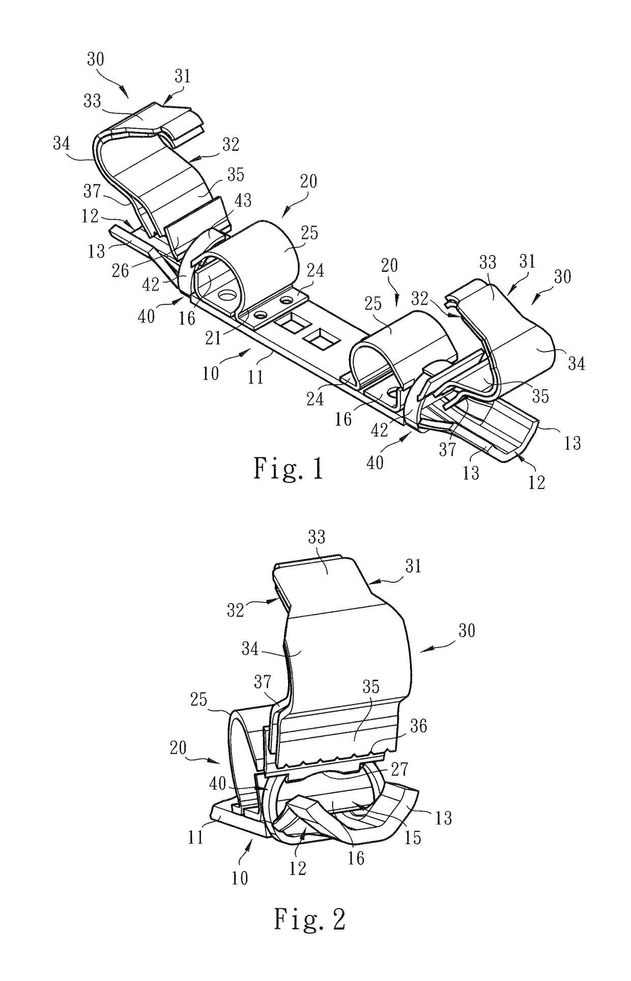
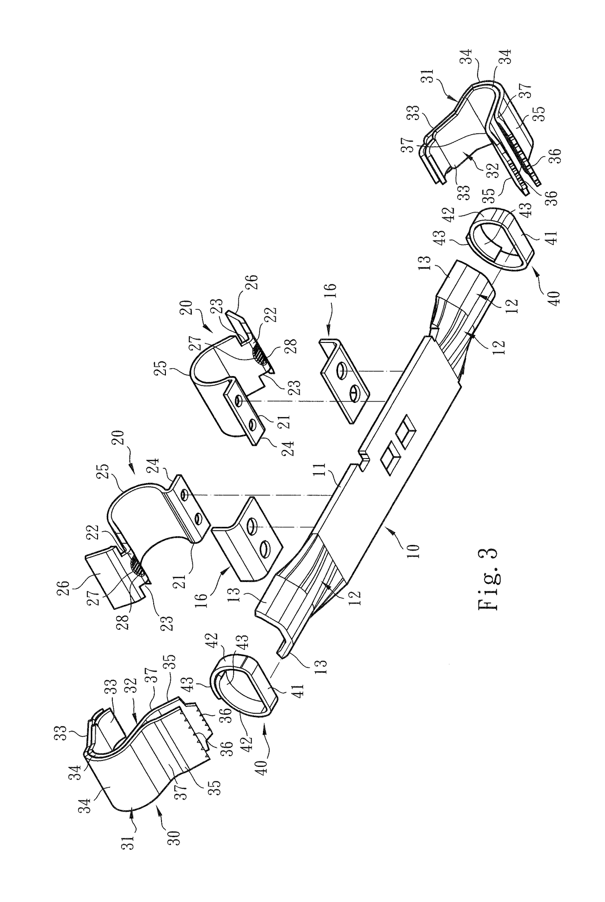
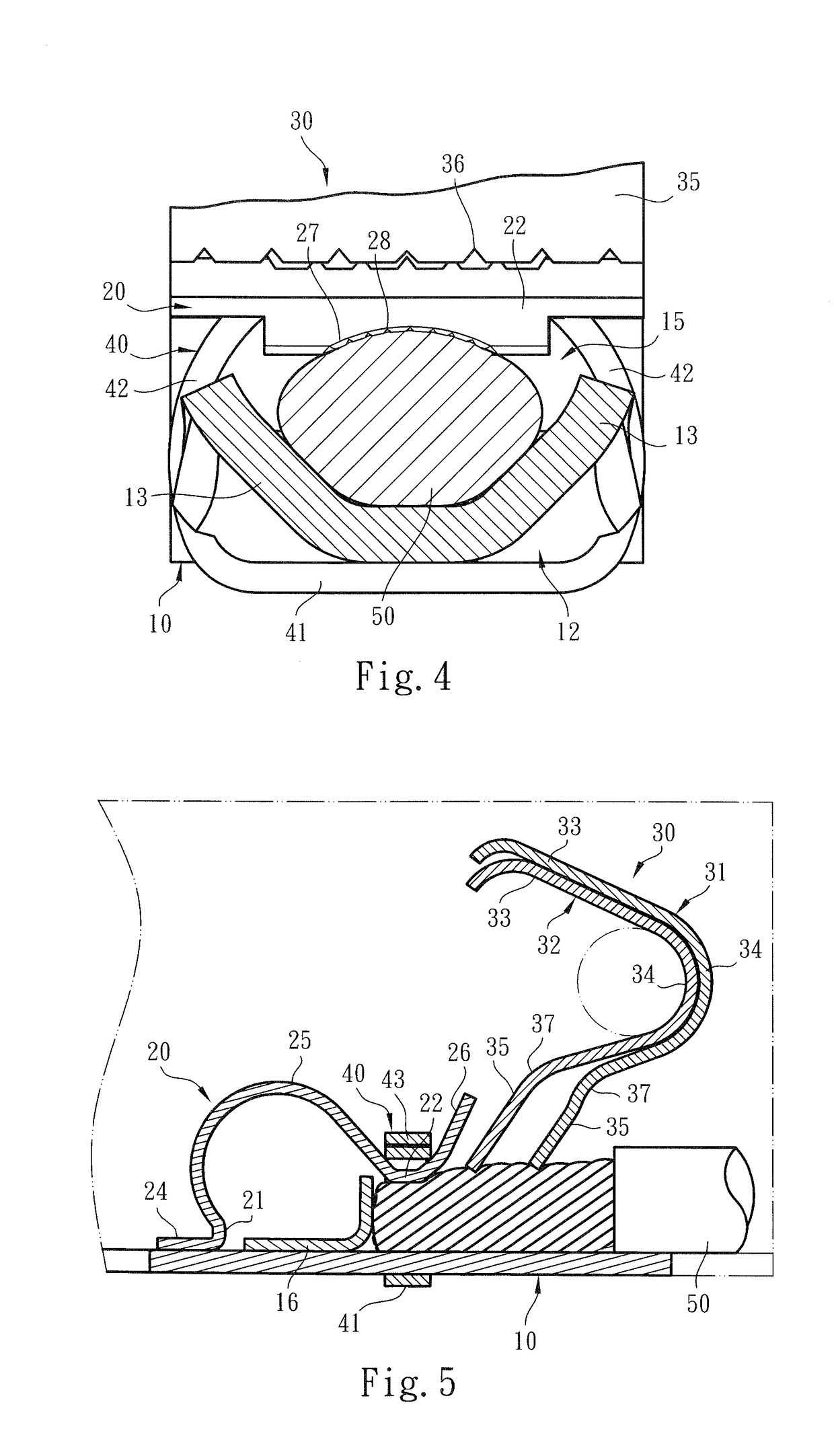
[0032]Please refer to FIGS. 1, 2 and 3. The conductive component structure for wire connection terminal of the present invention includes an assembly of a main body 10 and a restriction body 20. The conductive component (or the main body 10 and the restriction body 20) in cooperation with metal leaf springs 30 is mounted in a case (not shown) made of insulation material to form the wire connection terminal.

[0033]The upper section, upper side, lower section, lower side and lateral side mentioned hereinafter are recited with the direction of the drawings as the reference direction.

[0034]In a preferred embodiment, the main body 10 is selectively made of an electro-conductive material in the form of a plate body having lateral sides 11 and two end sections 12. The restriction body 20 is selectively made of an electro-conductive material (or metal material) with hardness greater than the hardness of the main body 10. The restriction body 20 can be integrally formed or assembled / disposed ...


PUM


Abstract

A conductive component structure for wire connection terminal has higher electro-conductive performance and is more securely assembled with the conductive wire. The conductive component includes a main body in the form of a plate body and a restriction body connected on the main body. The restriction body has a base section, a bow section connected with the base section and a free section connected with the bow section, which together provide elastic effect for the restriction body. When the conductive wire is plugged in to contact the conductive component, the restriction body guides the conductive wire and the rear end of the conductive wire is securely pressed and restricted between the main body and the restriction body.

Description

BACKGROUND OF THE INVENTION1. Field of the Invention[0001]The present invention relates generally to a conductive component structure for wire connection terminal, and more particularly to a conductive component having a restriction body for guiding the conductive wire and helping in securing the conductive wire.2. Description of the Related Art[0002]A conventional terminal device or wire pressing terminal has an insulation case (generally made of plastic material), a metal component (or so-called electrical conductive component) and a leaf spring conductor (or so-called metal leaf spring). The metal component and the leaf spring conductor are enclosed in the insulation case to press and electrically connect with or release a conductive wire plugged in the terminal device.[0003]Such electrical connection terminal devices include two types. The first type of electrical connection terminal device is inserted on a circuit board such as printed circuit board (PCB). The second type of el...

Claims


Application Information

Patent Timeline
IPC IPC(8): H01R4/48H01R4/26H01R13/24H01R11/28H01R9/24H01R13/432H01R13/502
CPCH01R4/4818H01R4/26H01R13/24H01R12/57H01R9/2416H01R13/432H01R13/502H01R11/28H01R4/489H01R4/48275H01R4/48185
Inventor WU, CHIH-YUANTAI, MING-SHAN
Owner SWITCHLAB
Learn More