
Multi-aperture imaging device, imaging system and method for capturing an object area

a multi-aperture imaging and object area technology, applied in the direction of printers, cameras, instruments, etc., can solve the problems of increasing the distance of the channel, limiting the miniaturization of the camera, and conventional cameras, so as to reduce the transition of stray light

Active Publication Date: 2019-01-10
FRAUNHOFER GESELLSCHAFT ZUR FOERDERUNG DER ANGEWANDTEN FORSCHUNG EV
View PDF0 Cites 15 Cited by
  • Summary
  • Abstract
  • Description
  • Claims
  • Application Information

AI Technical Summary

Benefits of technology

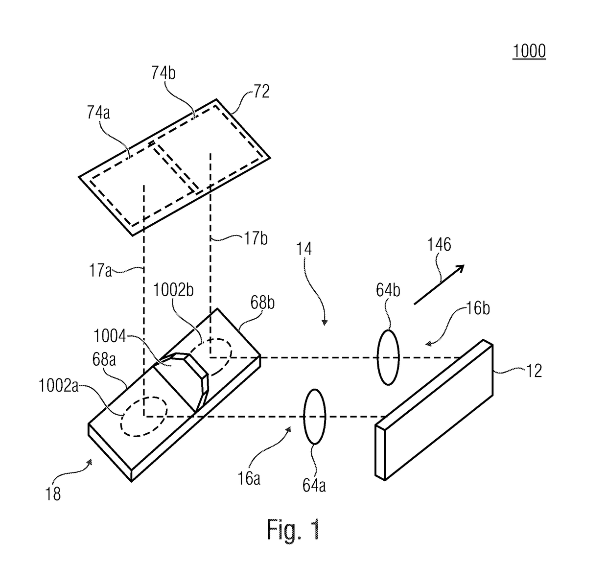
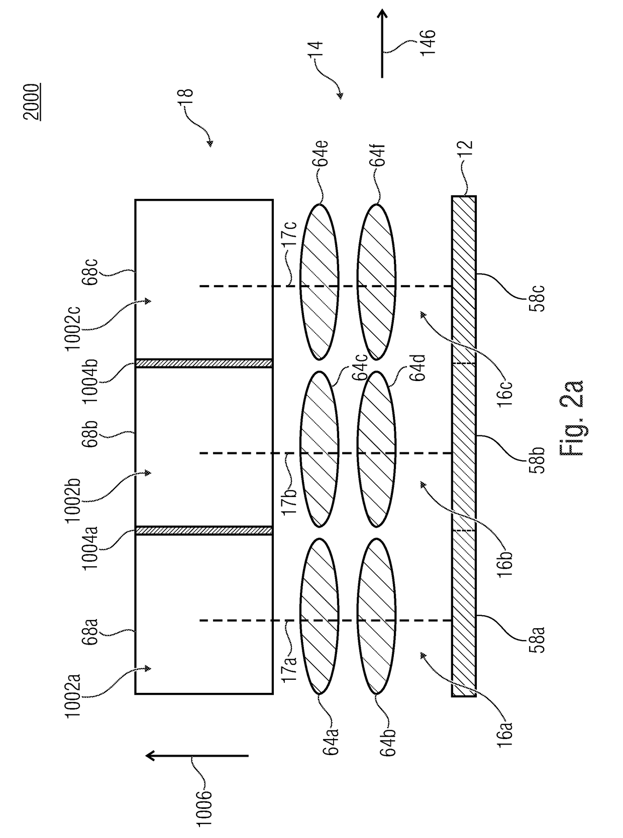
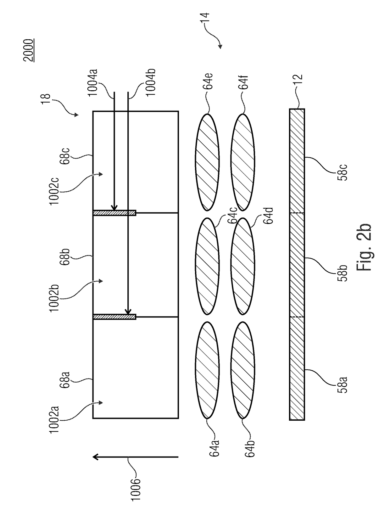
The present invention relates to a multi-aperture imaging device and a method for capturing an object area. The device includes an image sensor and an array of juxtaposed optical channels, each optical channel comprising optics for projecting at least one partial area of an object area on an image sensor area of the image sensor. The device also includes beam-deflecting means for deflecting an optical path of the optical channels in beam-deflecting areas of the beam-deflecting means. The invention provides a stray light suppressing structure between the beam-deflecting areas of adjacent facets to reduce transition of stray light between them, which allows for a smaller device size and higher image quality. The technical effects of the invention include improved image quality and reduced device size.

Problems solved by technology

Conventional cameras transmit the total field of view (object area) in one channel and are limited as regards to miniaturization.
However, this consequently increases the distance of the channels and results, all in all, to a large extension of the camera along the direction of the channel arrangement.

Method used


Image

  • Multi-aperture imaging device, imaging system and method for capturing an object area
  • Multi-aperture imaging device, imaging system and method for capturing an object area
  • Multi-aperture imaging device, imaging system and method for capturing an object area

Examples


Embodiment Construction

[0066]Before embodiments of the present invention will be discussed in detail below with reference to the drawings, it should be noted that identical, functionally equal or equal elements, objects and / or structures in the different figures are provided with the same reference numbers, such that the descriptions of these elements illustrated in the different embodiments are inter-exchangeable or inter-applicable.

[0067]Some of the embodiments described below relate to capturing an object area. Other embodiments described below relate to capturing a field of view. The terms object area / total object area and field of view or total field of view are to be considered as inter-changeable below. This means that the terms object area, total object area, field of view or total field of view are interchangeable without changing the meaning of the statements herein. To the same extent, the terms partial field of view and partial object area are interchangeable without changing the meaning of th...


PUM


Abstract

Multi-aperture imaging device includes at least one image sensor, an array of juxtaposed optical channels, wherein each optical channel has optics for projecting at least one partial area of an object area on an image sensor area of the image sensor, and a beam deflector for deflecting an optical path of the optical channels in beam-deflecting areas of the beam deflector. The beam deflector is formed as an array of facets arranged along a line-extension direction of the array of optical channels. One facet is allocated to each optical channel. Each facet has a beam-deflecting area. A stray light suppressing structure is arranged between a first beam-deflecting area of a first facet and a second beam-deflecting area of a juxtaposed second facet, which is configured to reduce transition of stray light between the first beam-deflecting area and the second beam-deflecting area.

Description

CROSS-REFERENCE TO RELATED APPLICATIONS[0001]This application is a continuation of copending International Application No. PCT / EP2017 / 055329, filed 10 Mar. 2017, which claims priority from German Application No. 10 2016 204 148.7, filed 14 Mar. 2016, which are each incorporated herein in its entirety by this reference thereto.BACKGROUND OF THE INVENTION[0002]The present invention relates to a multi-aperture imaging device, to an imaging system having at least one multi-aperture imaging device and to a method for capturing an object area.[0003]Further, the present invention relates to stray light suppression in multi-aperture imaging devices having a linear channel arrangement.[0004]Conventional cameras transmit the total field of view (object area) in one channel and are limited as regards to miniaturization. In smartphones, two cameras are used that are oriented in and opposite to the direction of the surface normal of the display. In known multi-aperture imaging systems, a contigu...

Claims


Application Information

Patent Timeline
Patent Type & Authority Applications(United States)
IPC IPC(8): G03B17/17H04N5/225G02B26/08G03B9/02H04N5/232G03B13/34H04N5/247G03B5/00H04N23/90H04N25/00
CPCG03B17/17H04N5/2254H04N5/2252G02B26/0816G03B9/02G03B2205/0015G03B13/34H04N5/247G03B5/00H04N13/207H04N5/23287G03B17/00H04N23/45H04N23/51H04N23/55H04N23/672H04N23/90H04N23/687
Inventor WIPPERMANN, FRANKBRUECKNER, ANDREASBRAEUER, ANDREAS
Owner FRAUNHOFER GESELLSCHAFT ZUR FOERDERUNG DER ANGEWANDTEN FORSCHUNG EV
Learn More