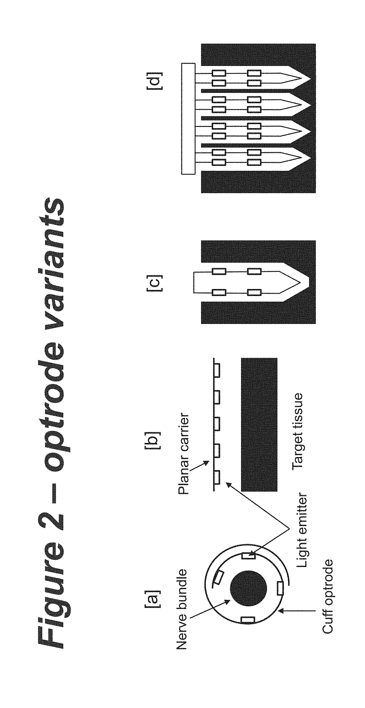
Temperature sensor

a technology of temperature sensor and sensor body, which is applied in the field of temperature sensor, can solve the problems of localized heating effect at the device surface, and achieve the effect of accurate determination

Active Publication Date: 2019-01-03
NEWCASTLE UNIV
View PDF2 Cites 5 Cited by
  • Summary
  • Abstract
  • Description
  • Claims
  • Application Information

AI Technical Summary

Benefits of technology

[0025]In some embodiments, the electrical circuit comprises one or more low pass filters to filter switching noise, whereby the photonic device temperature can be accurately determined despite variations in power supply noise.

Problems solved by technology

One key form of such a system is to generate light directly, but this can cause localized heating effects at the device surface which may need to be monitored.

Method used


Image

  • Temperature sensor
  • Temperature sensor
  • Temperature sensor

Examples


experimental verification

[0067

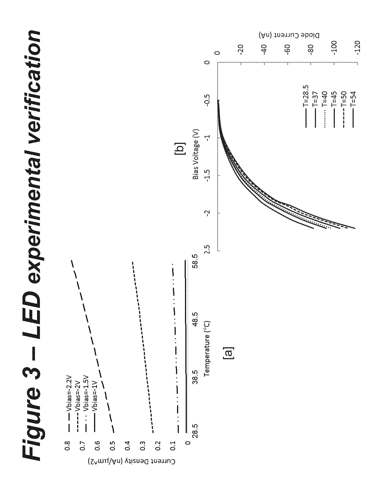
[0068]As the reverse current of LED is employed as temperature sensitive parameter to design the sensor we have experimentally explored GaN LEDs performance to investigate the linear relationship between junction temperature (Tj) and reverse current [15].

[0069]An LED test setup is implemented using GaN LED to extract the needed IR-T curve at different bias voltages. The LED under test is placed in an isolated dark box to guarantee that the measured current is only due to the temperature change. The box is also temperature isolated to ensure about the accuracy of the measured temperature. A hot plate is placed under the LED to increase the temperature which can be measured and recorded by the IR Optris PI camera and the camera interface software, respectively.

[0070]In a fixed reverse bias voltage across the LED, temperature is increased using the hot plat from 28° C. to 60° C. and the reverse current is measured. The measurement has been repeated for different bias voltages from...


PUM

PropertyMeasurementUnit
bias voltageaaaaaaaaaa
frequencyaaaaaaaaaa

Abstract

A temperature sensor comprising a light emitter, an electrical circuit for applying a reverse bias voltage across the light emitter and for measuring a reverse current, and means for calculating a temperature from the measured reverse current.

Description

FIELD OF INVENTION[0001]The present invention relates to temperature sensors and methods of sensing temperature. The invention relates in particular, but not exclusively, to temperature sensors integrated with implantable devices.BACKGROUND[0002]Implantable devices are becoming increasingly important in clinical practice. A key target area is in treating neurological deficit. For example pacemakers have been utilized since the 1950's to support proper function of cardiac muscle and have more recently been applied to the brain to treat tremor in conditions such as Parkinson's disease. Beyond neuroprosthetics there is also a need to monitor and stimulate other organs such as the Pancreas in the case of diabetes.[0003]Optical interrogation of cells and tissue has long been an important tool in ex-vivo studies. For example tissue staining methods have been around since the late 19th century. In the context of modern biomedical implantable devices, there are two key applications: opto-el...

Claims


Application Information

Patent Timeline
Patent Type & Authority Applications(United States)
IPC IPC(8): G01K7/01G01K7/42A61B5/01A61N5/06
CPCG01K7/01G01K7/427A61B5/01A61N5/0622G01K2217/00A61B2562/0271A61N2005/0612A61N2005/0627A61N2005/0652A61N2005/067A61B5/4041A61B5/4848A61N5/0601G01K2211/00A61N5/067
Inventor DEHKHODA, FAHIMEHDEGENAAR, PATRICKSOLTAN, AHMED
Owner NEWCASTLE UNIV
Why Eureka
Try Eureka