Linear vibration motor

a linear vibration and motor technology, applied in the field of consumer electronics, can solve the problems of affecting the vibration effect ineffectively, and achieve the effects of improving the acting force, intensive vibration effect, and maximizing the effective magnetic field of the vibration block

Active Publication Date: 2018-12-27
GOERTEK INC
View PDF0 Cites 3 Cited by
  • Summary
  • Abstract
  • Description
  • Claims
  • Application Information

AI Technical Summary

Benefits of technology

[0005]In view of the above problems, the purpose of the present invention is to provide a linear vibration motor, which utilizes a magnetic conductive structure additionally provided between a stator and a vibrator to concentrate and guide the magnetic field generated by the vibration block to the stator coil, so as to maximize the effective magnetic field of the vibration block, thereby improving the acting force between the vibrator and the stator and obtaining an intensive vibration effect.

Problems solved by technology

However, in the micro vibration motor of the above described structure, the magnetic field lines generated by the magnetic members in the vibrator are relatively dispersed, and the magnetic conductive strength between the vibrator and the stator is relatively weak, and correspondingly, the magnetic flux passing through the coil is also relatively small, thus the force generated thereby is relatively small, which disadvantageously affects the vibration effect.

Method used


Image

  • Linear vibration motor
  • Linear vibration motor
  • Linear vibration motor

Examples


Embodiment Construction

[0027]In the following description, for the purposes of explanation, various specific details are described in order to provide a full understanding of one or more embodiments. However, it is apparent that these embodiments can be implemented without these specific details. In other examples, well-known structures and apparatus are illustrated in form of block diagram in order to facilitate describing the one or more embodiments.

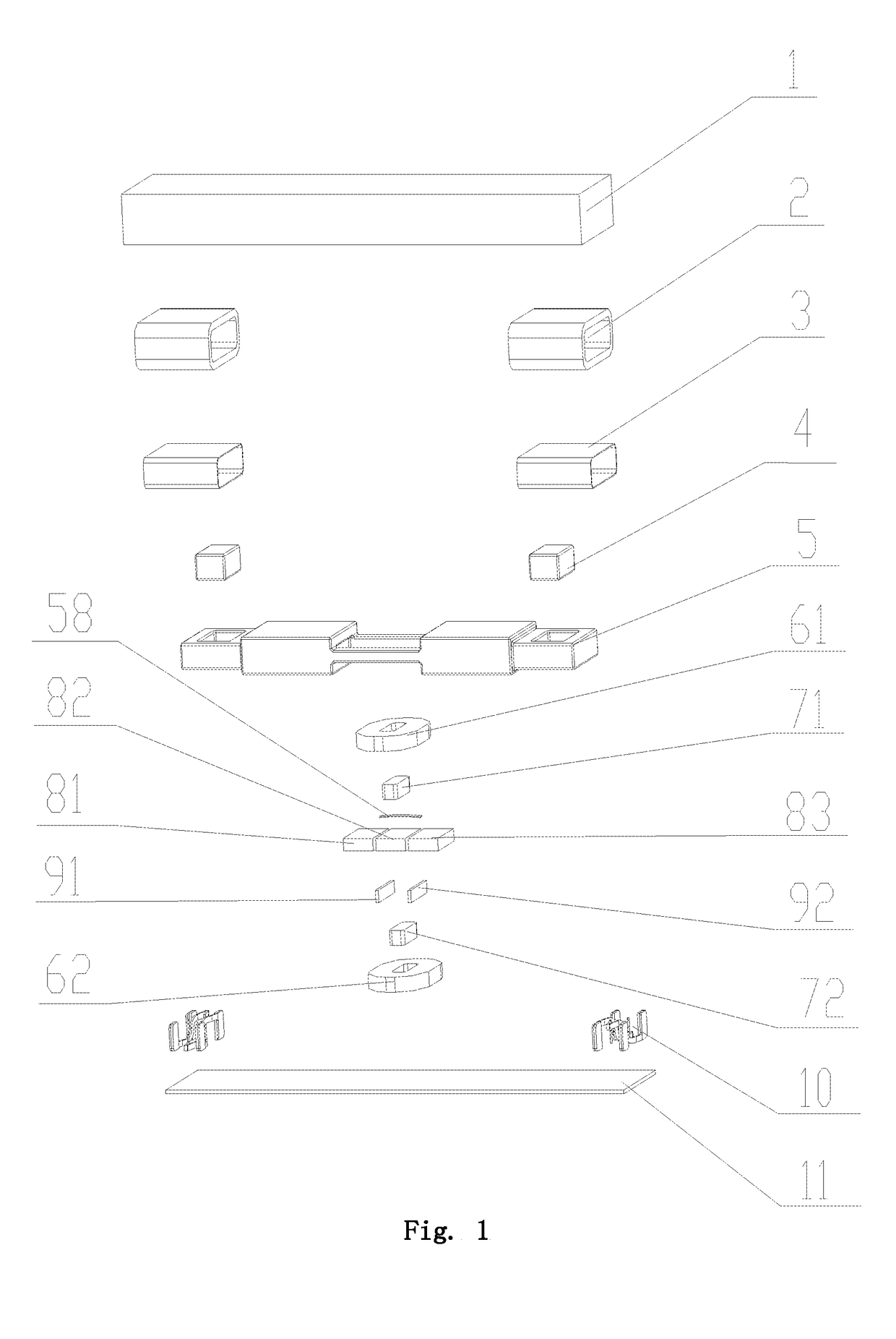
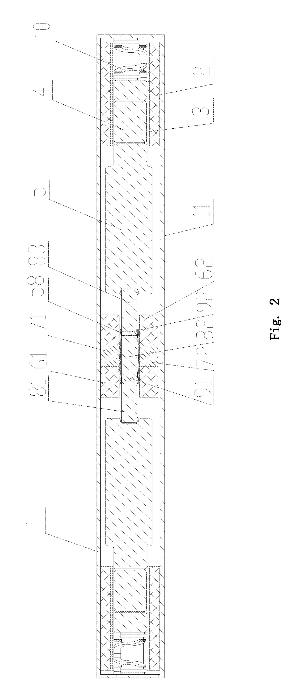
[0028]The “counterweight block” used in the following detailed description of embodiments may also be referred to as “mass block”, and both of them refer to a block having heavy mass and is made of high density metal which is fixed to a vibration block that generating vibration for vibration balance.

[0029]In addition, the present invention is mainly focus on the improvement in micro vibration motors, but it is not excluded that the technology disclosed in the present invention can be applied to a large vibration motor. However, in order to facilitate describ...


PUM


Abstract

A linear vibration motor includes a vibration block having permanent magnets and magnetic conductive yokes between adjacent permanent magnets; and a stator having stator coils arranged corresponding to the vibration block and magnetic conductive cores in the stator coils, a magnetic conductive brush being fixed on the magnetic conductive cores and a brush head of the brush being in elastic contact with the magnetic conductive yokes; or, a magnetic conductive brush being fixed on the magnetic conductive yokes and the brush head of the brush being in elastic contact with the magnetic conductive cores. The magnetic field lines generated by the vibration block can be concentrated to be conducted to the stator coils, thereby maximizing the effective magnetic field of the vibration block to improve the acting force between the vibrator and the stator and obtain an intensified vibration effect.

Description

TECHNICAL FIELD OF THE INVENTION[0001]The present invention relates to technical field of consumer electronic, and more particularly, relates to a linear vibration motor for portable consumer electronic products.BACKGROUND OF THE INVENTION[0002]With the development of communication technology, portable electronic products such as mobile phones, handheld game player or handheld multimedia entertainment apparatus have come up to people's lives. In these portable electronic products, micro vibration motors are generally used for providing system feedback, such as mobile phones notification on an incoming call, game player's vibration feedback and the like. However, with the development tendency for electronic products to be lightening and thinning, a variety of internal components thereof also need to suitable for this tendency, and micro vibration motor is no exception.[0003]The existing micro vibration motor generally comprises an upper cover, a lower cover which forms a vibration sp...

Claims


Application Information

Patent Timeline
Patent Type & Authority Applications(United States)
IPC IPC(8): H02K33/18
CPCH02K33/18H02K33/00
Inventor LIU, CHUNFAZU, FENGLEI
Owner GOERTEK INC
Why Eureka
Try Eureka