
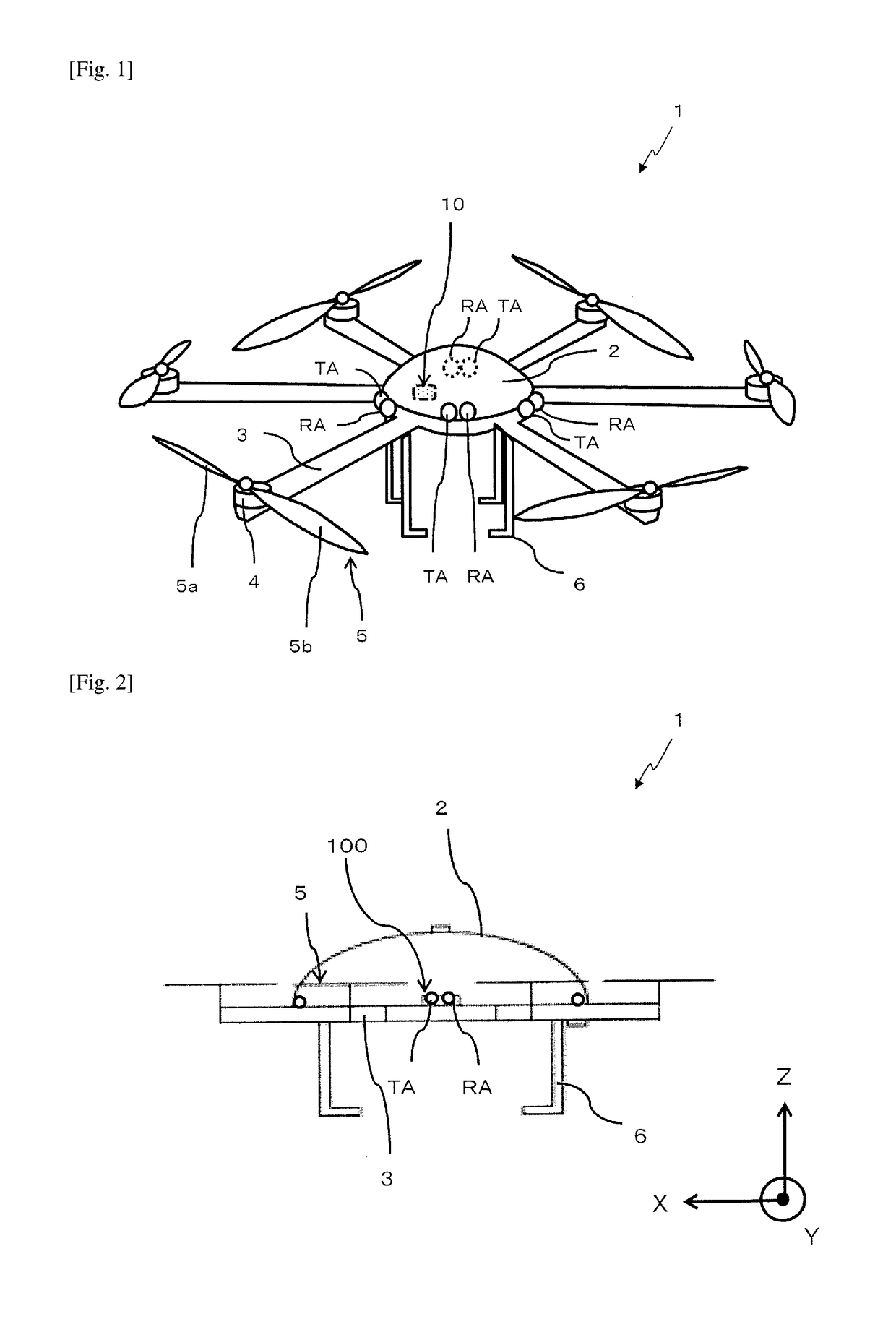
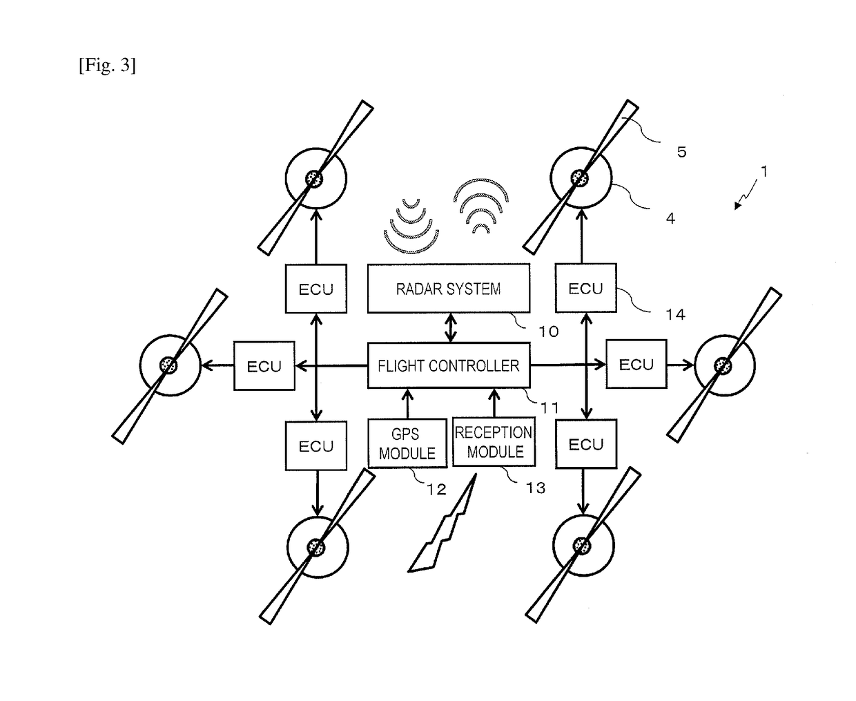
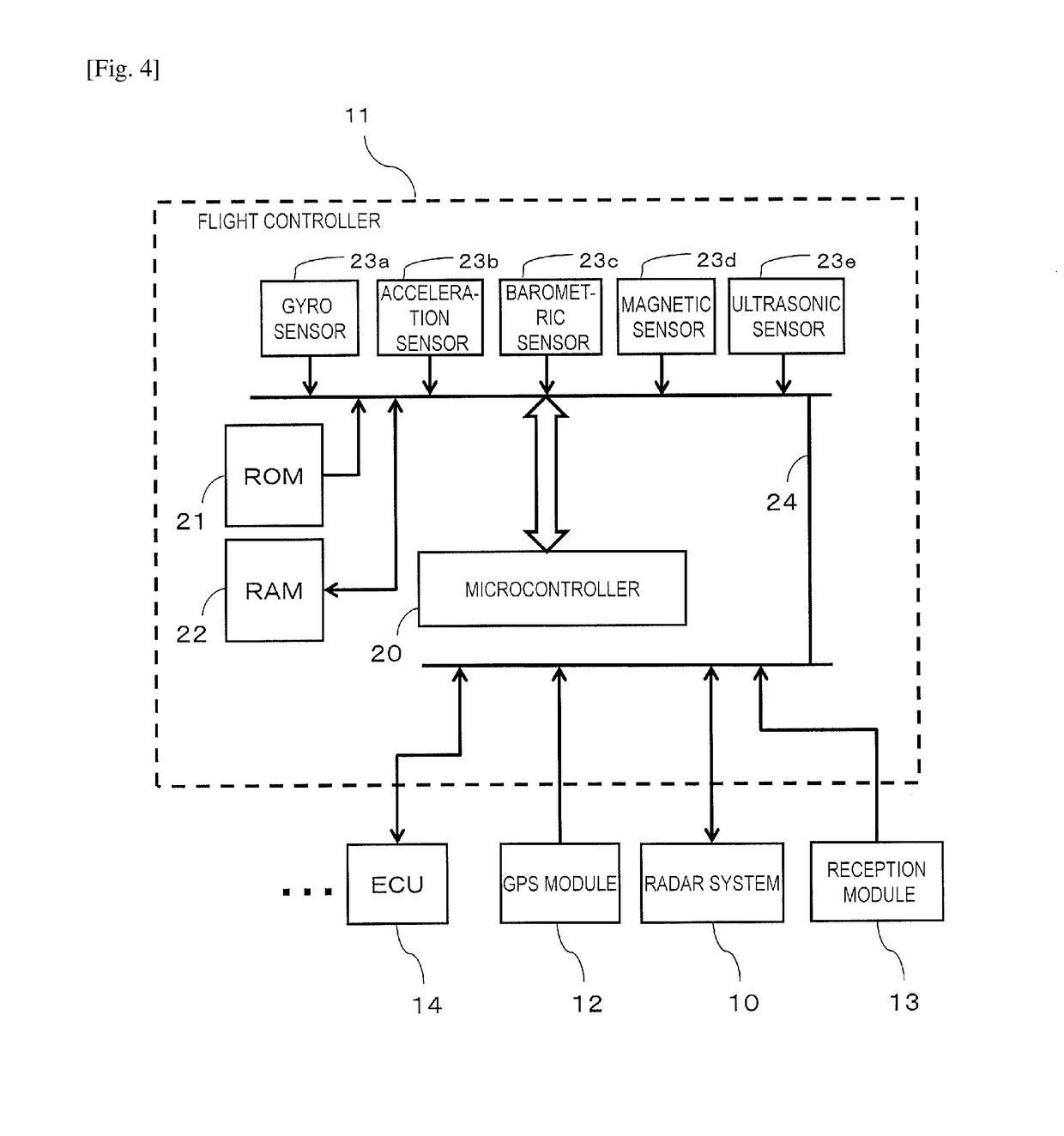
Multicopter with radar system

Inactive Publication Date: 2018-12-13
NIDEC CORP +1
View PDF0 Cites 11 Cited by
  • Summary
  • Abstract
  • Description
  • Claims
  • Application Information

AI Technical Summary

Benefits of technology

The patent describes a multicopter with a radar system that improves target detection by accounting for signals reflected off its rotors. This leads to a more accurate signal transmission and reception.

Problems solved by technology

However, even by utilizing the GPS, it is still not possible to accomplish flight while avoiding obstacles such as utility poles, power pylons, bridge piers, and so on.
Even if a multicopter is flown by utilizing a video taken by the camera, accidents of colliding with obstacles may still occur.
Particularly in the nighttime, when there is little light, it is difficult to identify objects or structures which do not emit light by themselves (e.g., trees) through the use of a video taken by the camera.

Method used


Image

  • Multicopter with radar system
  • Multicopter with radar system
  • Multicopter with radar system

Examples


embodiment 1

[0161]In the present embodiment, the radar system 10 performs a target detecting process at moments when the influence of a reflected wave originating from a rotor 5 is small.

[0162]FIG. 21 is a frequency spectrum chart showing a relationship between beat signals respectively corresponding to a reflected wave from the rotor 5 and reflected waves from targets, in a radar system 10 which operates by the FMCW method. In actuality, the frequency spectrum to be obtained will be a total of all waveforms in FIG. 21.

[0163]A reflected wave Rw from the rotor 5 (a “reflected wave originating from a rotor(s) 5”) has a very broad frequency spectrum because, as has been described with reference to FIG. 19 and FIG. 20, the peripheral velocity of the rotor 5 significantly varies with distance from the axis of rotation. In other words, the relative velocity between the antenna TA / RA and each minuscule point on the rotor 5 will have a very wide distribution. On the other hand, reflected waves (target-...

embodiment 2

[0174]The present embodiment will illustrate a process in which the object detection apparatus 40 transmits a signal wave at a moment when the angle or solid angle as any rotor 5 is viewed from the antenna TA / RA is equal to or smaller than the predetermined value. Based on a signal wave which is received by the reception antenna RA, the object detection apparatus 40 estimates a moment at which the angle or solid angle is equal to or smaller than the predetermined value, and causes a signal wave to be transmitted from the transmission antenna TA based on the estimation result. Even if the transmission antenna TA and the reception antenna RA are composed of separate antenna elements, the present embodiment will regard both as being at substantially the same position.

[0175]Note that the reception antenna RA in the present embodiment is composed of a one-dimensional array as shown in FIG. 6, and is able to detect an incident azimuth of a reflected wave. However, in order to detect a mom...

embodiment 3

[0224]In the present embodiment, the radar system 10 separates a reflected wave originating from a rotor 5 from a target-originated reflected wave, and by utilizing the target-originated reflected wave, performs signal processing for detecting a target. The present embodiment will mainly illustrate a process of separating between a reflected wave originating from a rotor 5 and a target-originated reflected wave. Once the target-originated reflected wave has been separated, the subsequent signal processing for target detection is as has been described above.

[0225]The (sweep) condition for a single frequency modulation of a frequency modulated continuous wave FMCW according to Embodiment 2, i.e., the amount of time required for modulation (sweep time), is 1 millisecond, with a modulation width of 250 MHz. However, the sweep time might be made as short as about 100 microseconds.

[0226]However, in order to realize the aforementioned sweep condition, not only the constituent elements rela...


PUM


Abstract

A multicopter includes: motors to respectively rotate three or more rotors; and a radar system to transmit and receive a signal wave and detect a target by using the signal wave. An object detection apparatus in the radar system transmits and receives a signal wave to perform a target detecting process. An antenna element is in a position to receive the transmission wave reflected off a rotor (a rotor-originated reflected wave). The signal wave received at the antenna element is inclusive of a target-originated reflected wave reflected off a target and a rotor-originated reflected wave. The apparatus determines whether or not a frequency band satisfying a predefined condition for identifying a frequency peak is contained in a frequency spectrum of the signal wave as received by the antenna element, and determines a peak of a frequency band satisfying the predefined condition to be a frequency of the target-originated reflected wave.

Description

[0001]This is a continuation of International Application No. PCT / JP2017 / 003789, with an international filing date of Feb. 2, 2017, which claims priority of Japanese Patent Application No. 2016-020771, filed on Feb. 5, 2016, Japanese Patent Application No. 2016-092619, filed on May 2, 2016, and Japanese Patent Application No. 2016-140348, filed on Jul. 15, 2016, the entire contents of which are hereby incorporated by reference.BACKGROUND1. Technical Field[0002]The present disclosure relates to a multicopter having a radar system mounted therein.2. Description of the Related Art[0003]Use of unmanned multicopters with three or more rotors is becoming increasingly widespread. Unmanned multicopter are used for photography, crop dusting, disaster investigation from the air, for example, and in recent years have been expected as a means for delivering articles. Unmanned aircraft such as unmanned multicopters are also referred to as UAVs (Unmanned Aerial Vehicles).[0004]Some unmanned multi...

Claims


Application Information

Patent Timeline
IPC IPC(8): G01S13/536B64C39/02G01S13/94G01S7/03G01S7/35G01S13/933G01S13/935
CPCB64C2201/027G01S13/536B64C39/024G01S7/032G01S2007/356G01S7/354B64C2201/141G01S13/94B64D47/00G01S7/02G01S7/03G01S13/345G01S13/862G01S15/08G01S15/88B64C1/36G01S13/933B64U2201/00B64U30/20B64U2201/10B64U2101/64B64U10/16B64U50/19B64U20/87G01S13/935
Inventor ICHINOSE, TAKESHIKAMO, HIROYUKIKIRINO, HIDEKIKITAMURA, HIDEAKI
Owner NIDEC CORP
Learn More