
A wall suppression method for through-wall detection based on phase-locked tracking loop

A technology for tracking loops and walls, applied in measuring devices, radio wave measurement systems, radio wave reflection/reradiation, etc., can solve wall parameter estimation errors, target and wall aliasing, and detection target position errors and other problems to achieve the effect of proper signal-to-noise ratio, avoiding detection target position error, and accurate target detection

Active Publication Date: 2017-03-01
XIAN UNIV OF TECH
View PDF4 Cites 0 Cited by
  • Summary
  • Abstract
  • Description
  • Claims
  • Application Information

AI Technical Summary

Problems solved by technology

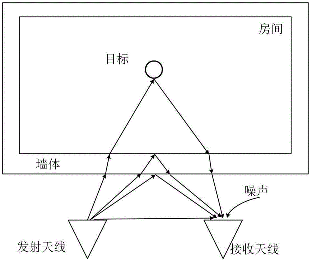
[0004] The object of the present invention is to provide a wall-through-wall detection wall suppression method based on a phase-locked tracking loop, which solves the problem of wall parameter estimation errors in the prior art that lead to detection target position errors, and the target and wall confusion in the echo signal. Overlapping makes it impossible to separate target information

Method used


Image

  • A wall suppression method for through-wall detection based on phase-locked tracking loop
  • A wall suppression method for through-wall detection based on phase-locked tracking loop
  • A wall suppression method for through-wall detection based on phase-locked tracking loop

Examples


Embodiment 1

[0035] The present invention compares the detection ability of the target at different distances from the wall with the traditional spread spectrum radar. The two sets of system antennas transmit the same signal, the M sequence frequency is 1.023GHz, and the carrier center frequency is 955.8MHz. The distance between the target and the wall is compared respectively. Detection capability at 3m, 1m, 30cm, such as Figure 5 shown. Figure 5 The left column in the middle is the radar adopting the traditional technology spread spectrum, and the right column is the radar adopting the method of the present invention. Figure 5 Figures (a) and (b) are the time-domain correlation diagrams of the traditional spread spectrum radar and the proposed radar when the distance between the target and the wall is 3m. Figure 5 (c)(d) is Figure 5 (a) Partial enlarged picture of (b), in addition to the direct wave signal and the wall reflected wave signal, the target reflected wave information c...

Embodiment 2

[0037]The invention compares the detection capabilities under different signal-to-noise ratios with traditional spread spectrum radars. The two sets of system antennas transmit the same signal, the M sequence frequency is 1.023GHz, and the carrier center frequency is 955.8MHz. The detection capabilities when the signal-to-noise ratio is 40dB, 20dB, 0dB, -10dB, and -20dB are compared respectively, as shown in Figure 6 shown. Figure 6 The left column in the middle is the radar adopting the traditional technology spread spectrum, and the right column is the radar adopting the method of the present invention. Figure 6 Figures (a) and (b) are the time-domain correlation diagrams of the traditional spread spectrum radar and the proposed radar when the signal-to-noise ratio is 40dB, from Figure 6 It can be seen from the figure that in the traditional spread spectrum radar, the target echo information is almost submerged in the noise, but the target echo information is very obvi...


PUM


Abstract

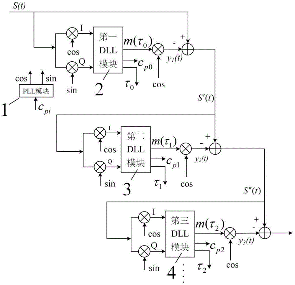
The invention discloses a wall-penetrating detection wall suppression method based on a phase-locked tracking loop. The steps include: 1) multiplying the original echo signal received by the receiving antenna with the local carrier sin and cos generated by the PLL module, After the carrier is stripped, it is divided into two channels of signals; 2) Send the two channels of signals into the first DLL module together, after calculating the delay phase τ of the M sequence, output the M sequence, multiply it with the carrier cos output by the PLL module, and obtain the direct wave signal; 3) subtracting the received original signal from the direct wave signal to obtain the direct signal; 4) passing through multiple DLL modules in turn, repeating the processing methods from step 1) to step 3), and finally obtaining the target echo information, Serve. The method of the invention is applied to the wall-penetrating radar, and the signal-to-noise ratio is suitable, and the target detection is accurate.

Description

technical field [0001] The invention belongs to the technical field of radar through-wall detection, and relates to a wall suppression method for through-wall detection based on a phase-locked tracking loop. Background technique [0002] The through-wall radar transmits electromagnetic waves of specific frequencies to penetrate and detect non-transparent media such as walls, wood boards, and trees. Electromagnetic waves of 0.5GHz to 3GHz have a good penetrating ability to walls and will not harm the human body. Through-the-wall radar can pass through concrete walls, slate walls, and wooden walls, etc., and has a wide range of applications in post-disaster rescue, hostage rescue, and urban combat. In the imaging of through-wall radar, due to the existence of the wall, when the electromagnetic wave penetrates the wall, the electromagnetic wave will be reflected, refracted and changed in speed, resulting in time delay, attenuation and distortion of the signal; the image of the ...

Claims


Application Information

Patent Timeline
Patent Type & Authority Patents(China)
IPC IPC(8): G01S7/36
CPCG01S7/354G01S7/36G01S13/888G01S7/358
Inventor 席晓莉郑晨宋忠国张学辉
Owner XIAN UNIV OF TECH
Learn More