An electromechanical brake calliper actuator

a technology of electromechanical brakes and actuators, applied in the direction of actuators, braking systems, braking elements, etc., can solve the problems of limiting the deformability of the actuator, compromising the efficiency and/or mechanical integrity of the device, and fatigue of the service life of the components, so as to maximize the efficiency of the actuator formed by the screw-nut screw-piston assembly

Active Publication Date: 2018-12-13
FRENI BREMBO SPA
View PDF1 Cites 2 Cited by
  • Summary
  • Abstract
  • Description
  • Claims
  • Application Information

AI Technical Summary

Benefits of technology

[0020]This configuration, while allowing the compensation of the misalignment between the longitudinal axes of nut screw and piston, inhibits the mutual rotation between the piston and nut screw, as well as between piston and calliper body, while preserving the design correlation “α-c”.
[0021]In this way, efficiency of the actuator formed by the screw-nut screw-piston assembly is maximized.

Problems solved by technology

This reaction causes a misalignment between the screw axis and piston axis, compromising the efficiency and / or mechanical integrity of the device due to the uncompensated stresses on the support and transmission components.
This misalignment of the axes can cause a non-uniform distribution of the load on the axial bearing supporting the screw and an imperfect distribution of the load on the rolling elements interposed between screw and nut screw, with consequent inhomogeneous Hertzian pressures on the balls, and thus problems related to the service life fatigue of the components.
To overcome this defect, the stiffness of the calliper body can be increased, thus limiting its deformability.
However the known solutions, which typically provide for the application of conical or spherical joints at the interface between the nut screw and the piston, cannot inhibit a possible partial rotation of the piston relatively to the nut screw because it is possible that, at the articulated joint between the nut screw and piston, there will be a mutual sliding between the contact surfaces, giving rise to an angular shift between piston and nut screw.
The implementation of rigid interfaces (for example by threading, interference etc.), useful to ensuring the link “α-c”, would result in an over-dimensioning of the mechanical parts due to the stresses resulting from the inability of the components themselves to compensate for the deformations of the brake calliper under load.
However, the prior art does not offer solutions advantageous for avoiding the phase shift between the nominal link “α-c” and link “α-c” under operating conditions (i.e., when the calliper exerts a braking action on the disc), exploiting for example only the coupling surfaces between piston and nut screw.

Method used


Image

  • An electromechanical brake calliper actuator
  • An electromechanical brake calliper actuator
  • An electromechanical brake calliper actuator

Examples


Embodiment Construction

[0033]Before explaining in detail a plurality of embodiments of the invention, it should be clarified that the application of the invention is not limited to its construction details and the configuration of the components presented in the following description or illustrated in the drawings. The invention is able to assume other embodiments and to be practically implemented or realized in different ways.

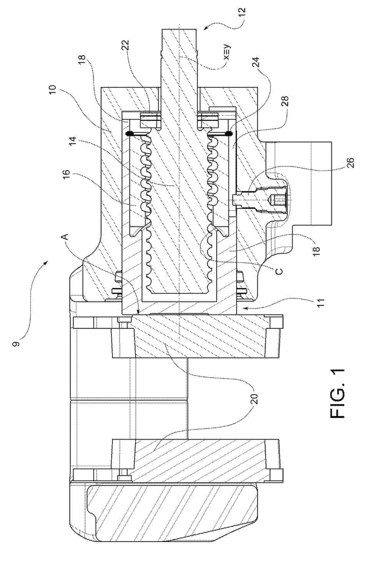
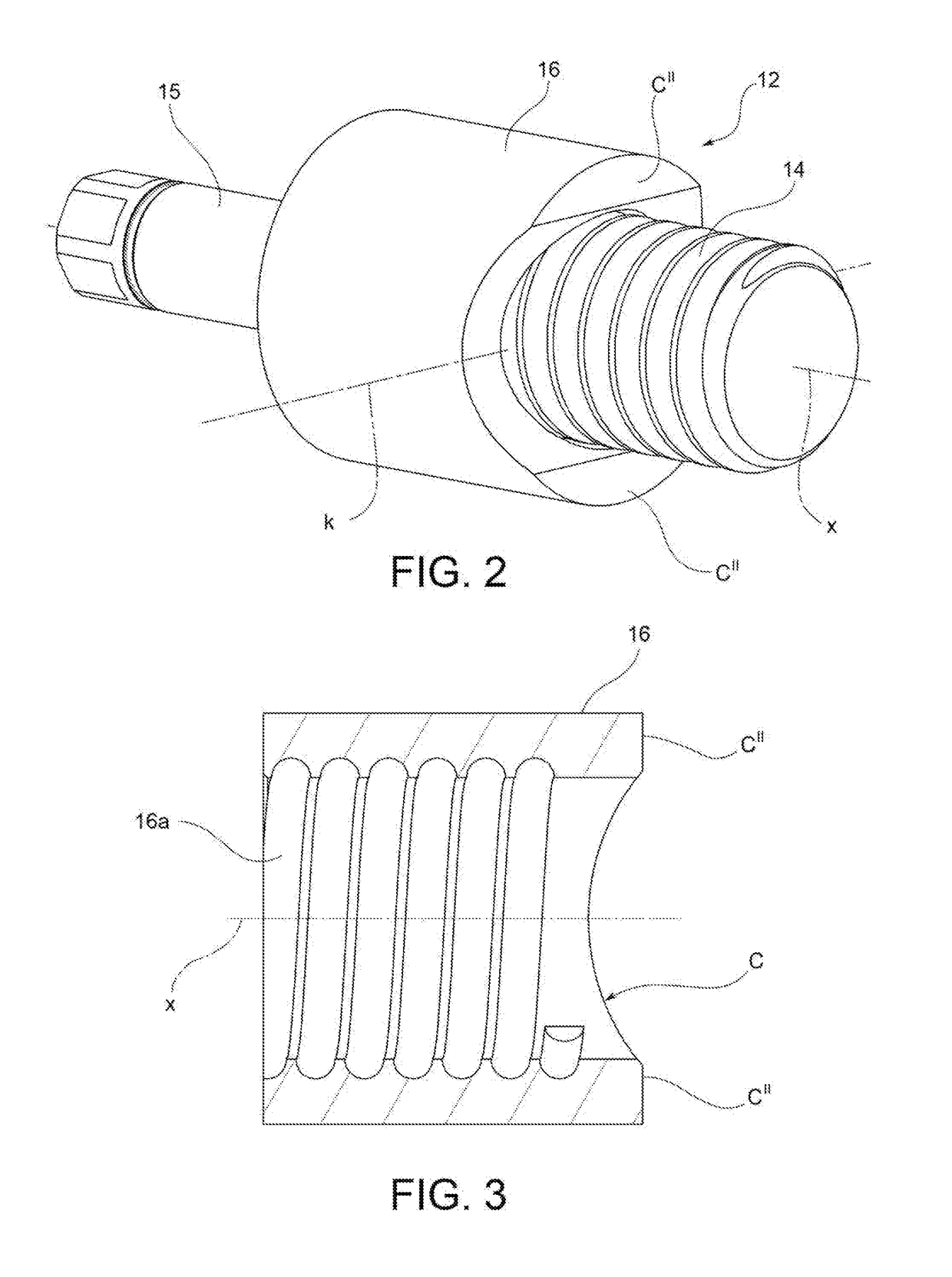
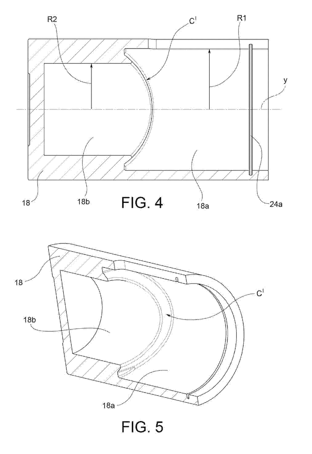
[0034]Referring initially to FIG. 1, an electromechanical brake calliper 9 comprises a calliper body 10 inside which is housed a mechanical actuator 11 that includes, according to a preferred embodiment of the invention, a recirculating ball screw 12 and a movable thrust element 18,32. The recirculating ball screw 12 comprises a screw 14, rotatable about a first longitudinal axis x, which screw is associated in rotation to a nut screw 16 which, in function of the rotation of the screw 14, can move with a reciprocating motion along a direction parallel to said first longitudinal axis...


PUM


Abstract

An electromechanical brake caliper (9) includes a caliper body (10) and an electromechanical actuator (11). The electromechanical actuator includes a screw (14) and a nut screw (16) coupled to it, so that the nut screw (16) engages a movable thrust element (18, 32) by coupling surfaces (C, C′ and CIV) that cooperate with each other in the thrust relationship. This configuration allows oscillation of the relative nut screw (16) with respect to the movable thrust element (18, 32) about a single transverse axis (k), impeding the relative rotation between the nut screw (16) and the piston (18) about a longitudinal axis (y) of the thrust element.

Description

TECHNICAL SECTOR[0001]This invention pertains, in general, to the field of braking systems; in particular, the invention relates to an actuator for an electromechanical brake calliper.STATE OF THE ART[0002]The technical field of application of this invention is that of electromechanical brake callipers, which generally require an electrical actuation, a reduction system and a system for converting the motion from rotary to translatory.[0003]The conversion of the motion takes place by means of the meshing between a rotatable screw housed in a caliper body or calliper body, and a nut screw, usually by means of circulating balls in the interface between screw and nut screw, in so-called recirculating ball screws.[0004]The rotation of the screw imparts a translational motion to the nut screw, which pushes a piston that engages one of a pair of brake pads, mounted on the calliper body symmetrically with respect to a brake disc; the pressure of the pads on the disc generates a braking act...

Claims


Application Information

Patent Timeline
Patent Type & Authority Applications(United States)
IPC IPC(8): F16D65/18F16D65/00
CPCF16D65/18F16D65/0068B60T13/741F16D55/226F16D2055/0016F16D2121/14F16D2121/24F16D2125/40F16D2125/66F16D2125/36F16D2125/06
Inventor SALA, PAOLOPAGANI, LUCA
Owner FRENI BREMBO SPA
Why Eureka
Try Eureka