
Vehicle control system

a control system and vehicle technology, applied in the direction of mechanical equipment, driver input parameters, transportation and packaging, etc., can solve the problems of easy shock depending on a condition, large inertia due to the decrease in the rotational speed on the input side, etc., to prevent an increase in vibration

Active Publication Date: 2018-12-13
MAZDA MOTOR CORP
View PDF0 Cites 2 Cited by
  • Summary
  • Abstract
  • Description
  • Claims
  • Application Information

AI Technical Summary

Benefits of technology

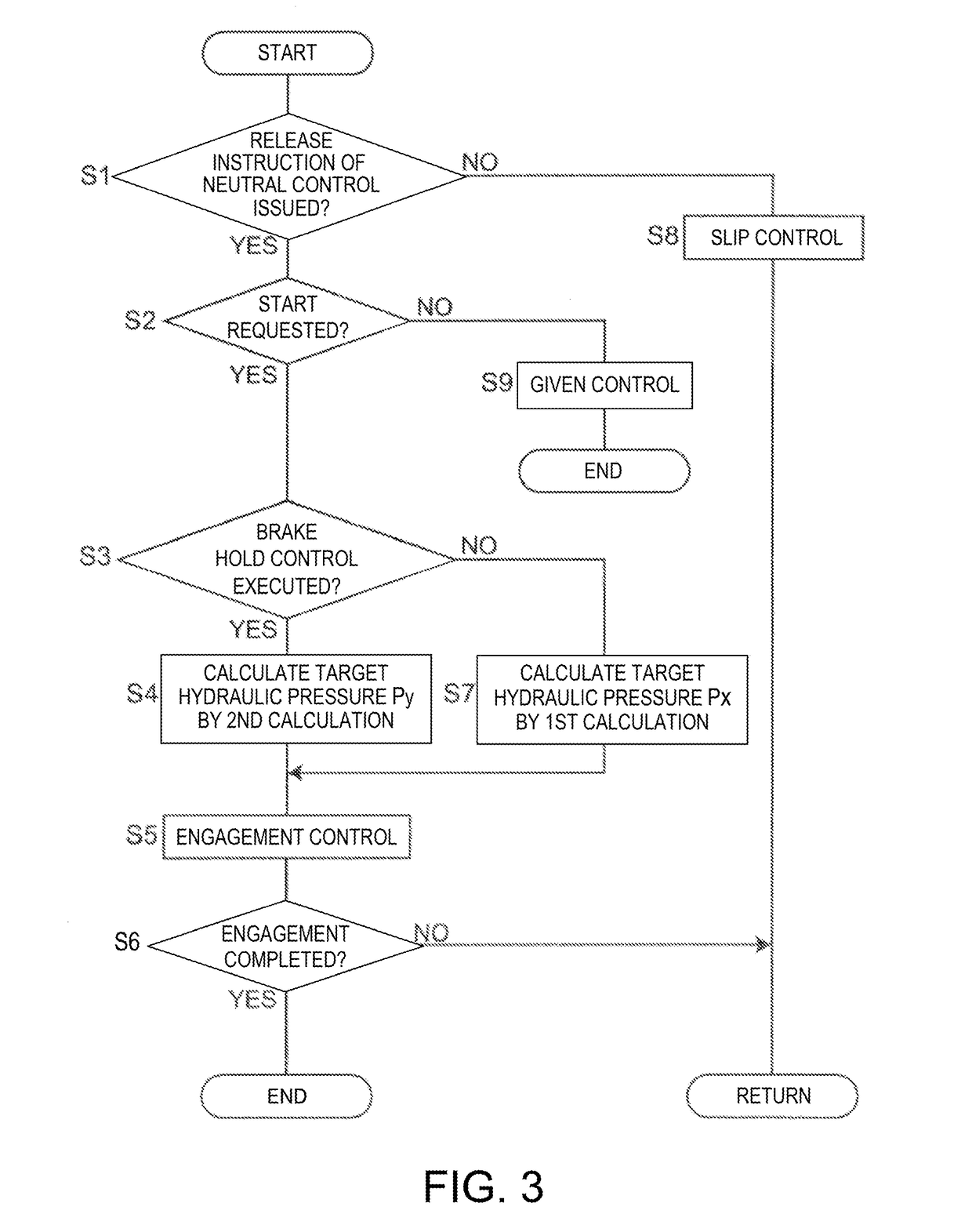
The present disclosure aims to provide a vehicle control system that prevents shocks when a vehicle starts from a stopped state where a neutral idle control and a brake hold control are executed. By using a second calculation to control the hydraulic pressure supply to the frictional engageable element, the engagement of the frictional engageable element is delayed, resulting in effective prevention of shocks compared to the case where the hydraulic pressure control is performed using the same calculation as when the vehicle starts from the vehicle stopped state where the brake hold control is not executed. Additionally, the use of the centrifugal pendulum damper reduces impacts and vibrations caused by suspending operations of one or some of the cylinders of the engine. The technical effects of the patent text are improved vehicle control and reduced shocks during start-up.

Problems solved by technology

Incidentally, the present inventors found an issue that a shock easily occurs depending on a condition when starting a vehicle from a stopped state where the neutral control and the brake hold control described above are executed.
Therefore, the inertia due to the decrease in the rotational speed on the input side tends to become large.

Method used


Image

  • Vehicle control system
  • Vehicle control system
  • Vehicle control system

Examples


Embodiment Construction

[0045]Hereinafter, one embodiment of the present disclosure is described with reference to the accompanying drawings.

[Overall Configuration]

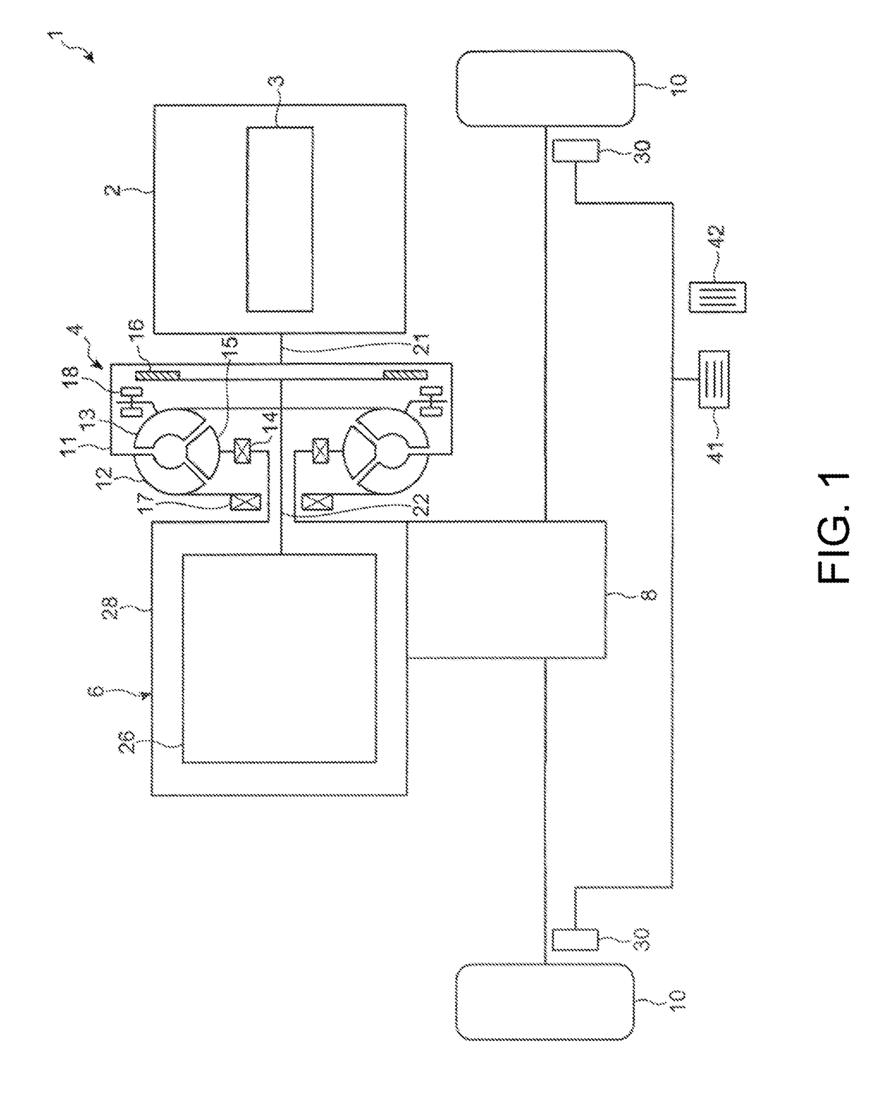
[0046]FIG. 1 is an overall view schematically illustrating a drive system of a vehicle 1 including a control system according to one embodiment of the present disclosure. As illustrated in FIG. 1, the vehicle 1 includes an engine 2 as a drive source, a torque converter 4 as a fluid coupling, an automatic transmission 6 which changes an output torque of the engine 2 transmitted via the torque converter 4.

[0047]Note that although FIG. 1 illustrates a so-called transversely-placed drive system in which the engine 2, the torque converter 4, and the automatic transmission 6 are arranged in width directions of the vehicle, the drive system of the vehicle 1 may be vertically placed so that the engine 2, the torque converter 4, and the automatic transmission 6 are arranged in front-and-rear directions of the vehicle.

[0048]The engine 2 is a reciprocating...


PUM


Abstract

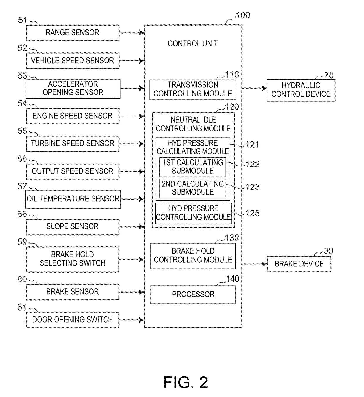
A control system of a vehicle is provided, which includes an automatic transmission, a brake controller, and a processor configured to execute a neutral idle controlling module, a hydraulic pressure calculating module, a hydraulic pressure controlling module to calculate a target value of hydraulic pressure supplied to a frictional engageable element according to a given parameter, and a brake hold controlling module. The calculating module includes a first calculating submodule executed to calculate the target value in a period from an issuance of a vehicle start request when a neutral idle control is executed and a brake hold control is not executed in a vehicle stopped state until the frictional engageable element is engaged, and a second calculating submodule executed to calculate the target value so that a calculated value is lower than in the first calculation when the value of the parameter is the same.

Description

TECHNICAL FIELD[0001]The present disclosure relates to a vehicle control system, which performs a neutral idle control and a brake hold control, and is directed to a technical field of a vehicle drive control.BACKGROUND OF THE DISCLOSURE[0002]For an automatic transmission which transmits an engine output via a torque converter, a neutral idle control (hereinafter, simply referred to as “the neutral control”) for automatically bringing the automatic transmission into a neutral state by controlling a frictional engageable element for a starting gear position to a disengaged state while a vehicle is stopped within a D-range (drive range or forward drive range), is known. When executing the neutral control, a turbine of the torque converter rotates following an engine operation at no load or an extremely low load; therefore, compared to the stopped state within a first gear range in which the turbine is fixed, the load of the torque converter and an engine load are reduced and fuel effi...

Claims


Application Information

Patent Timeline
Patent Type & Authority Applications(United States)
IPC IPC(8): B60W30/192B60W10/18B60W30/20B60W10/02
CPCB60W30/192B60W10/18B60W30/20B60W10/02B60W2540/12B60W2540/10B60W2510/1005B60W2520/04B60W2710/1005B60W2710/1083F16H61/02F16H61/20F16H2061/207F16H61/061F16H61/04
Inventor TASAKA, MITSUKAZUSAITO, TADASHIIMAI, SHOJINAKAYAMA, YASUNARI
Owner MAZDA MOTOR CORP
Learn More