
Electromagnetic relay

Active Publication Date: 2018-12-06
ANDEN CORP
View PDF5 Cites 4 Cited by
  • Summary
  • Abstract
  • Description
  • Claims
  • Application Information

AI Technical Summary

Benefits of technology

The present disclosure aims to enhance the degree of design freedom and ensure a predetermined passage area while keeping a flame-extinguishing function. The conventional electromagnetic relay may have limitations in positioning the vent hole which restricts its design. However, this patent proposes a solution to overcome this issue and allow the position of the vent hole to be set without being influenced by the position of the terminal insertion hole, thereby enhancing the design flexibility. Moreover, the dimensions of the vent hole can also be set without being affected by the width dimension of the terminal, which makes it easier to ensure the flame-extinguishing function and the predetermined passage area.

Problems solved by technology

However, the conventional electromagnetic relay may have a limitation in position of the vent hole, and a degree of freedom of design may reduce.
Therefore, when a width of the terminal is small, and a width of the vent hole is set to be smaller than or equal to the predetermined dimension for flame extinguishment, the predetermined passage area of the vent hole is difficult to be ensured.

Method used


Image

  • Electromagnetic relay
  • Electromagnetic relay
  • Electromagnetic relay

Examples


first embodiment

[0029]An electromagnetic relay according to a present embodiment can be used for an electric vehicle on which a fuel cell is mounted. The fuel cell utilizes hydrogen gas which is one of flammable gas.

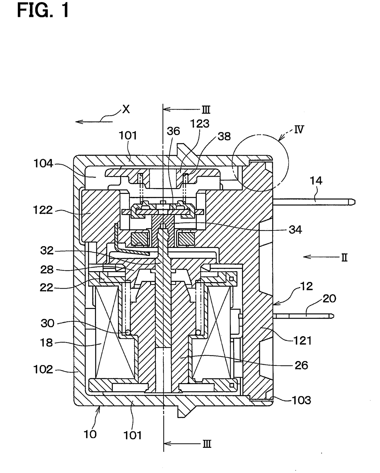
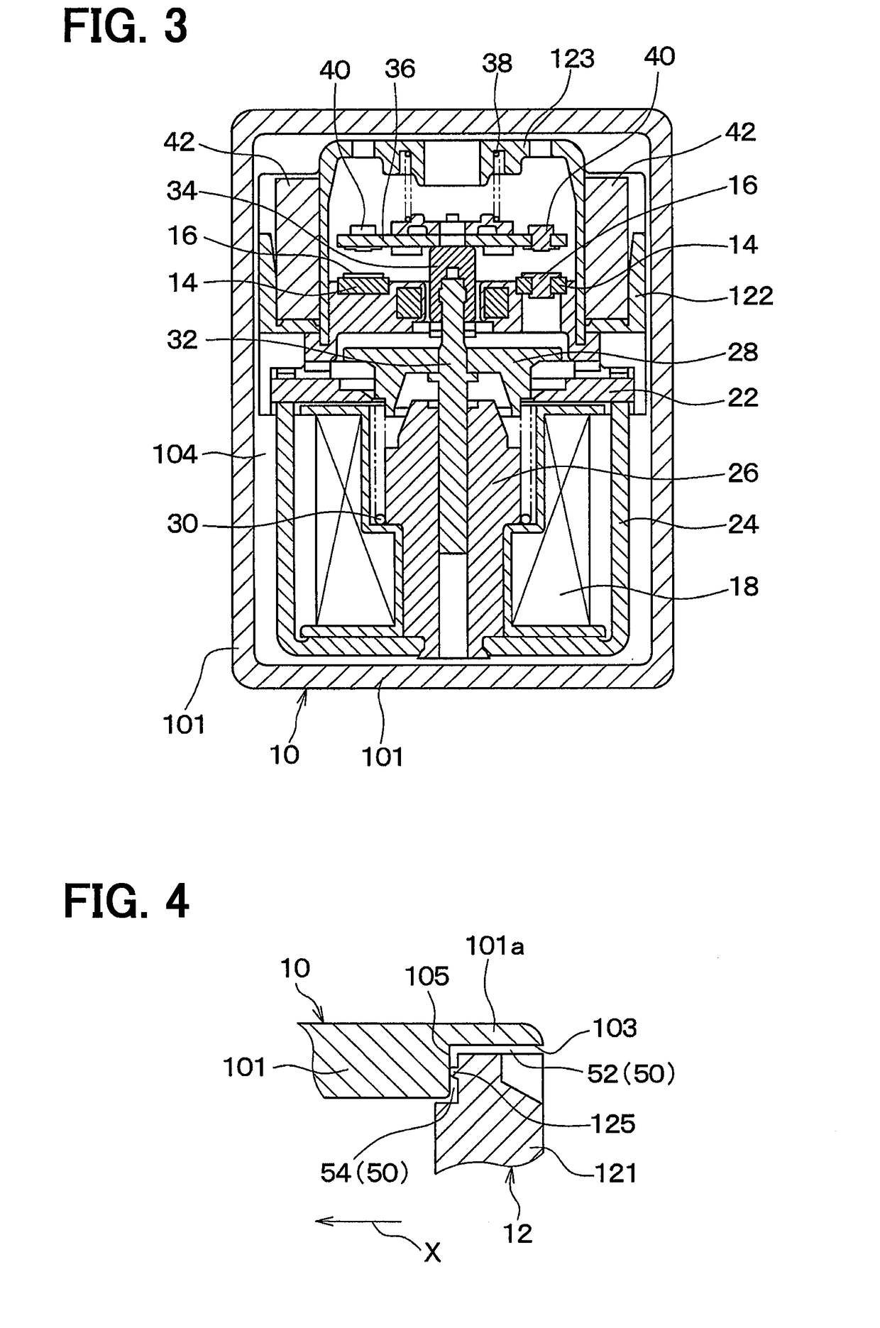
[0030]As shown in FIGS. 1 to 3, the electromagnetic relay of the present embodiment includes a casing 10 made of resin. The casing 10 includes four casing side walls 101 and one casing bottom 102. The casing 10 has a casing opening 103 on a side of the casing 10 facing the casing bottom 102. The casing 10 has a bottomed rectangular cylindrical shape. A housing space 104 is provided inside the casing 10, and the housing space 104 is open through the casing opening 103 to an external to the casing 10.

[0031]A base 12 made of resin includes a base bottom 121 joined to the casing 10 to close the casing opening 103, a base body 122 protruding from the base bottom 121 toward the casing bottom 102, and a base spring support 123 supporting a pressing spring 38 described later. The housing space ...

second embodiment

[0062]A second embodiment will be described with reference to FIG. 7. In the present embodiment, the positions of the vent holes 50 are different from those of the first embodiment. In the present embodiment, explanations of portions similar or equivalent to portions of the first embodiment will be omitted or simplified.

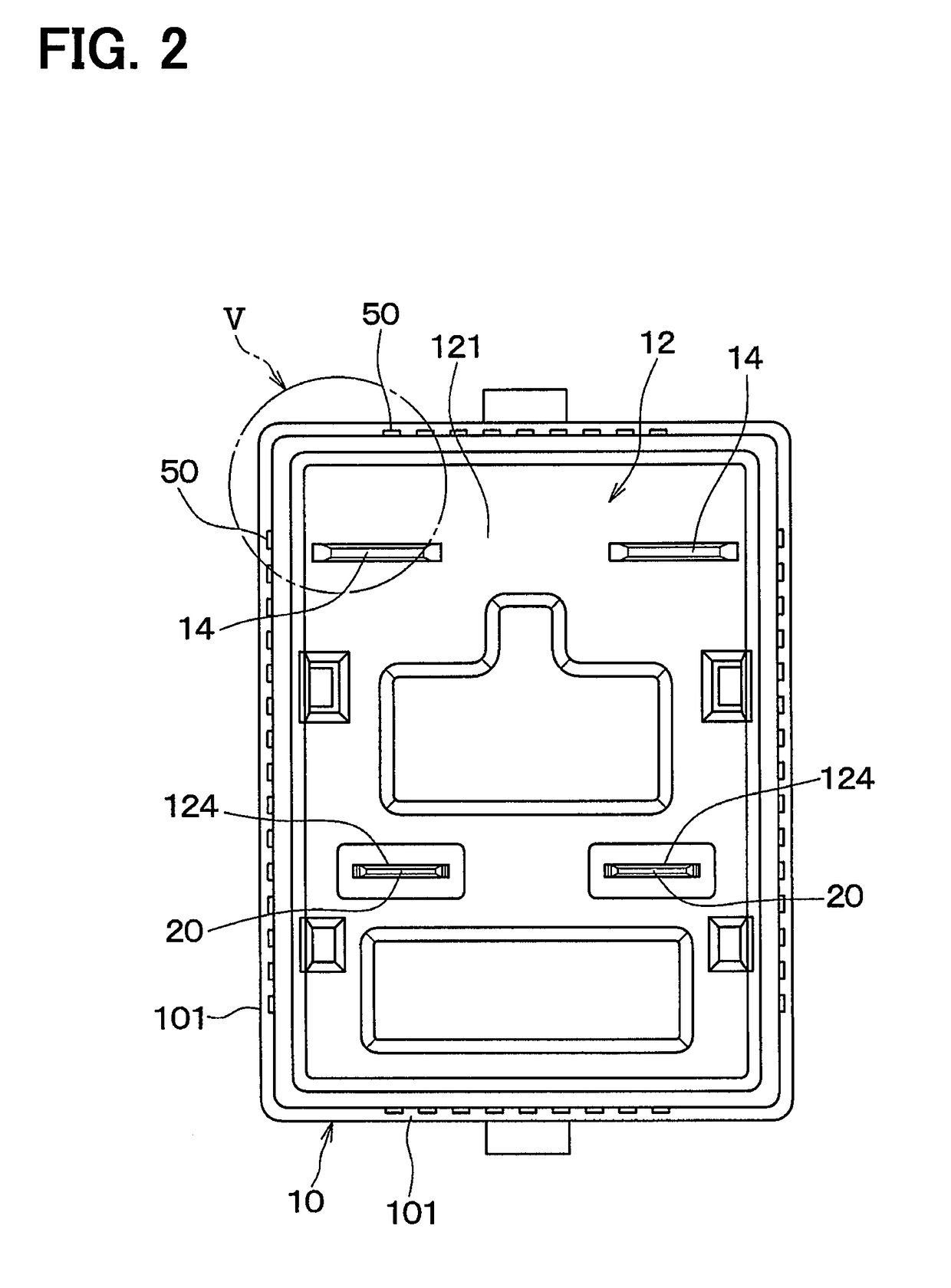
[0063]As shown in FIG. 7, in the present embodiment, a vent hole 50 is provided on a single casing 10, through which a housing space 104 (refer to FIG. 1) communicates with an external. More specifically, the vent hole 50 is a rectangular elongated slit extending through a casing side wall 101. A dimension S of a short side of the vent hole 50 is set to a dimension making it possible to extinguish flame passing therethrough.

[0064]When flame caused by an electric arc through ignition of flammable gas passes through the vent hole 50, heat of the flame is drawn by the casing 10, and the flame cannot be kept and extinguished.

[0065]According to the present embodiment, a p...


PUM


Abstract

An electromagnetic relay includes a casing having a housing space open to an external to the casing through an opening. A base is joined to the casing to close the opening. A coil, a pair of fixed contact elements and a pair of movable contact elements are housed in the housing space. A vent hole set to a dimension making it possible to extinguish flame passing therethrough is formed in a portion where the casing and the base are joined together.

Description

CROSS REFERENCE TO RELATED APPLICATION[0001]This application is based on and incorporates herein by reference Japanese Patent Application No. 2015-212057 filed on Oct. 28, 2015.TECHNICAL FIELD[0002]The present disclosure relates to an electromagnetic relay which opens or closes an electric circuit.BACKGROUND ART[0003]A conventional electromagnetic relay includes a casing having a housing space open to an external through an opening, and a base attached to the casing to close the opening. The housing space communicates with the external through a vent hole formed on the base.[0004]The base has a terminal insertion hole into which a terminal is inserted. The terminal insertion hole and the vent hole are next to each other to communicate with each other. Thus, when flame generated inside the housing space passes through the vent hole, the base and the terminal extinguish the flame by drawing heat from the flame (refer to Patent Literature 1, for example).PRIOR ART LITERATUREPatent Lite...

Claims


Application Information

Patent Timeline
IPC IPC(8): H01H50/12H01H50/02H01H50/54H01H9/04H01H50/64H01H50/14
CPCH01H50/12H01H50/02H01H50/541H01H9/047H01H50/64H01H50/14H01H9/342H01H50/023
Inventor TANAKA, TOMOAKIKAMIYA, MAKOTOKAMIYA, MIKIHIRO
Owner ANDEN CORP
Learn More