
Device that can be assembled by coupling

Active Publication Date: 2010-07-01
MAKO SURGICAL CORP
View PDF45 Cites 54 Cited by
  • Summary
  • Abstract
  • Description
  • Claims
  • Application Information

AI Technical Summary

Benefits of technology

[0009]Another embodiment of the invention relates to a device that can be assembled by coupling. The device includes first and second body members and positioning structure. The first and second body members are designed to be fastened relative to each other. The positioning structure is designed to provide an interface between the first and second body members, and to limit the position of the first and second body members relative to each other in six degrees of freedom. The positioning structure includes a first projection, a second projection, and a third projection. The first projection is on one of the first and second body members, and corresponding first and second surfaces are on the other of the first and second body members. Contacts between the first projection and the first and second surfaces at least partially define first and second contact areas that each are substantially linear. The second projection is on the one of the first and second body members, and a corresponding third surface is on the other of the first and second body members. Contact between the second projection and the third surface at least partially defines a third contact area that is substantially linear. The first and second projections and the first, second, and third surfaces are collectively designed such that the contacts between the first projection and the first and second surfaces and the contact between the second projection and the third surface limit the position of the first and second body members relative to each other in five degrees of freedom. The third projection is on the other of the first and second body members, and a corresponding fourth surface is on the one of the first and second body members. The third projection and the fourth surface are collectively designed such that contact between the third projection and the fourth surface limits positioning of the first and second body members relative to each other in a sixth degree of freedom, in a first translational direction.

Problems solved by technology

As such, during assembly of the robotic surgical system, the end effector and its mount on the robotic arm are assembled as a calibrated pair using specialized calibration equipment to achieve a high degree of precision and repeatability when mounting the end effector to the robotic arm, which may be a time-consuming and laborious process, even for specialists.
Thus, the end effector and mount lack interchangeability, meaning that the end effector cannot be reliably coupled to other mounts and vice versa.

Method used


Image

  • Device that can be assembled by coupling
  • Device that can be assembled by coupling
  • Device that can be assembled by coupling

Examples


Embodiment Construction

[0023]Presently preferred embodiments of the invention are illustrated in the drawings. An effort has been made to use the same or like reference numbers throughout the drawings to refer to the same or like parts.

[0024]The present invention relates to a device that can be assembled by coupling. The device can be particularly advantageous in a robotic surgical system. Although this specification describes the device in the environment of a robotic surgical system, it should be understood that the device is applicable to other types of robotic systems, including those used for surgical and non-surgical applications, as well as to non-robotic systems or applications. The present invention is not limited to the details or methodology set forth in the description or illustrated in the figures.

Overview of a Robotic Surgical System

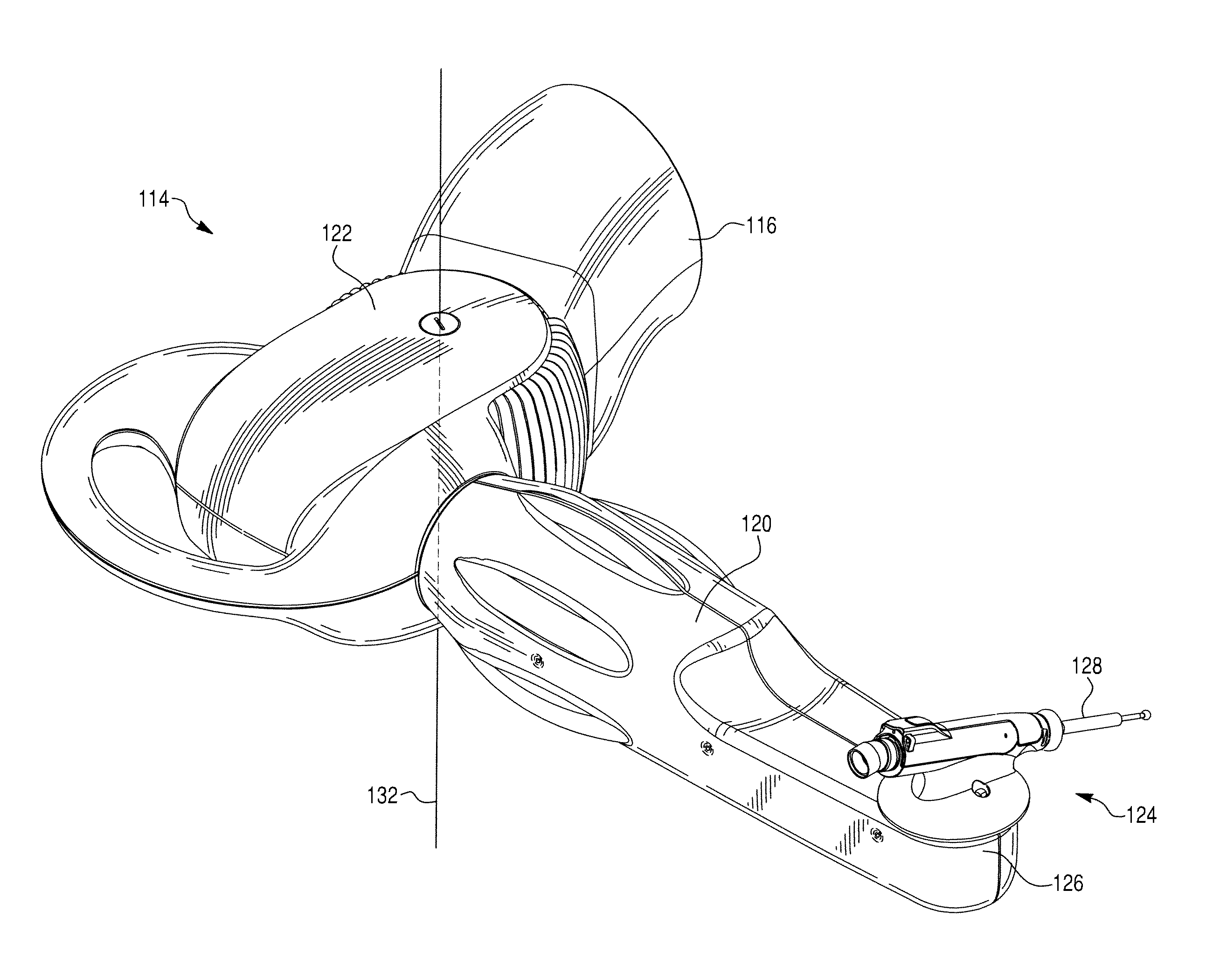
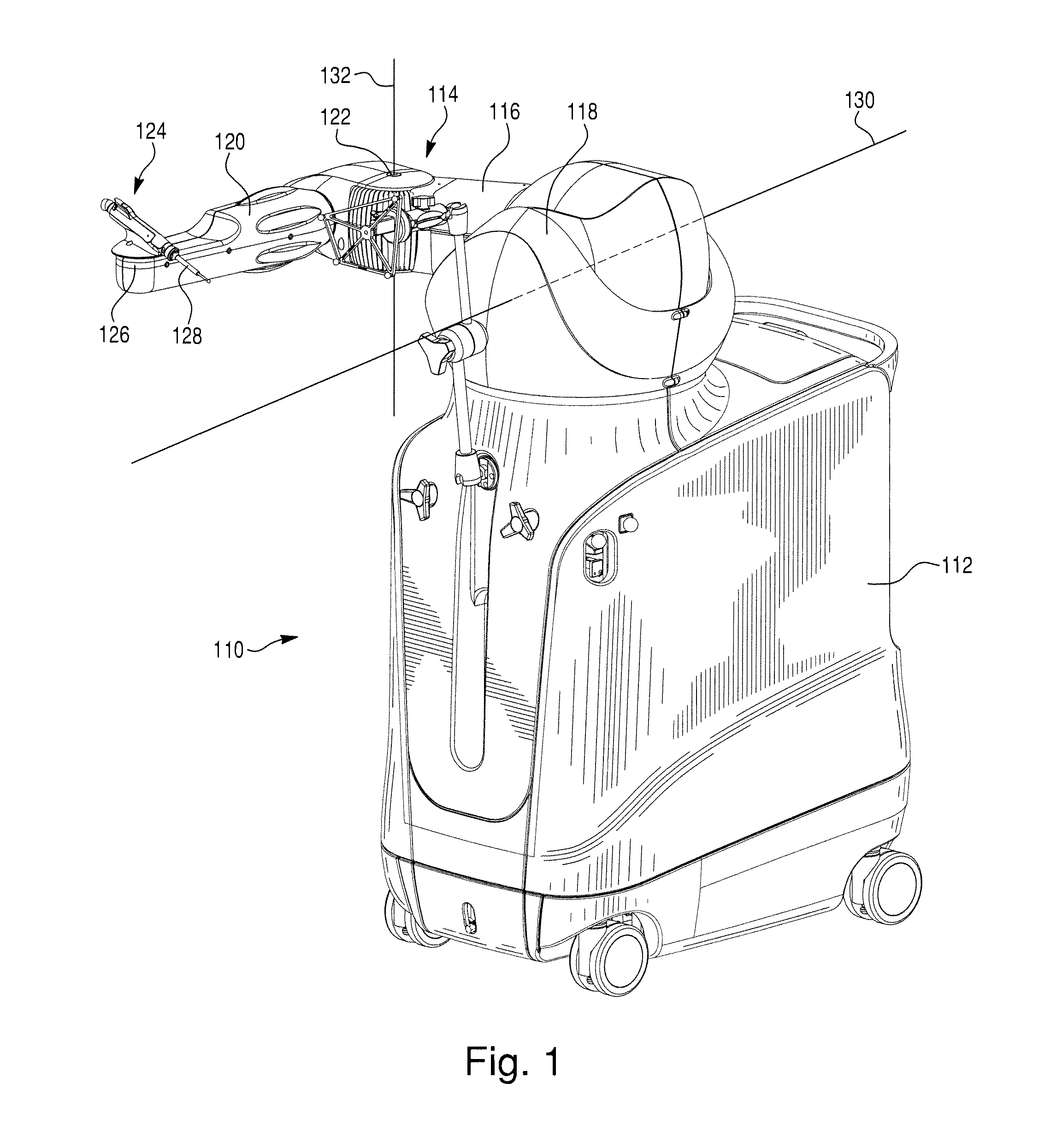
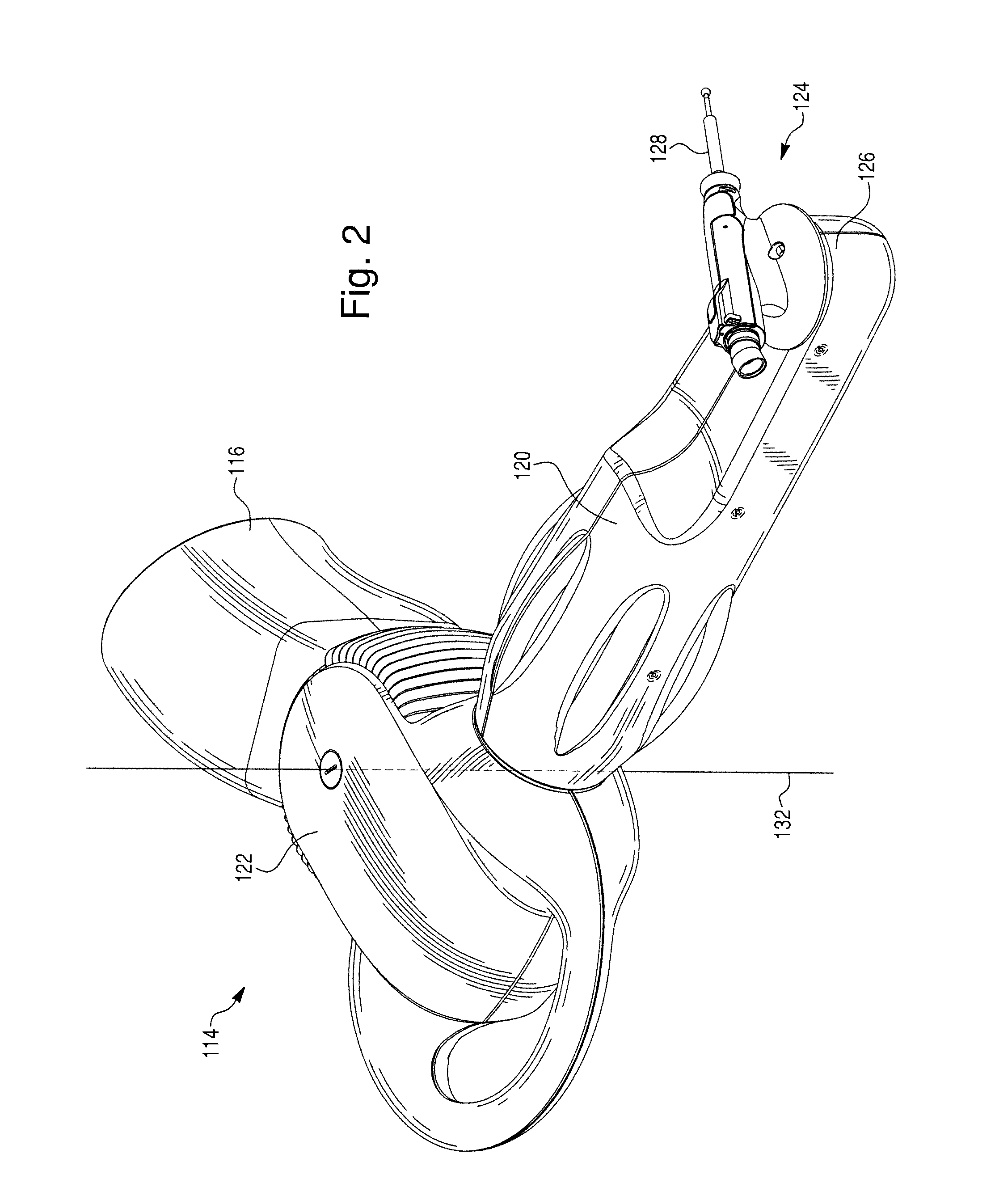
[0025]FIGS. 1 and 2 illustrate an example of a robotic surgical system 110 in which a device according to the present invention can be used. The robotic surgical...


PUM

PropertyMeasurementUnit
Angleaaaaaaaaaa
Angleaaaaaaaaaa
Shapeaaaaaaaaaa

Abstract

A device can be assembled by a coupling. The device includes first and second body members and positioning structure. The first and second body members are designed to be coupled relative to each other. The positioning structure is designed to provide an interface between the first and second body members, and to position the first and second body members relative to each other via first, second, and third contact areas. The first, second, and third contact areas are each substantially linear and are collectively configured to receive loads, and to limit positioning of the first and second body members relative to each other with regard to five degrees of freedom. A fourth contact area between the first and second body members is designed to limit positioning of the first and second body members relative to each other in a sixth degree of freedom, in a first translational direction.

Description

CROSS-REFERENCE TO RELATED PATENT APPLICATIONS[0001]This application claims priority to U.S. Provisional Patent Application Ser. No. 61 / 203,475, filed on Dec. 23, 2008, which is hereby incorporated by reference in its entirety.BACKGROUND[0002]1. Field of Invention[0003]The present disclosure relates generally to the field of devices that can be assembled by coupling. As a more specific example, the present disclosure relates to devices that can be assembled by coupling to connect an end effector to a robotic arm of a robotic surgical system.[0004]2. Description of Related Art[0005]A robotic surgical system may perform surgical tasks, including providing haptic feedback or maneuvering a surgical tool to, for example, assist in removing tissue (e.g., bone) or producing an incision. The surgical tool can be attached to an end effector that is coupled to a mount on an arm of the robotic surgical system.[0006]Because of the precision generally required for surgical tasks, a control syste...

Claims


Application Information

Patent Timeline
IPC IPC(8): F16D1/12
CPCA61B17/32002A61B2017/00477A61B2034/715A61B34/71A61B90/50A61B34/30Y10T403/32057Y10T403/32631Y10T74/20329Y10T74/20305Y10T403/32622Y10T74/20323Y10T29/53961
Inventor BENNETT, RICHARDKANG, HYOSIGSCHMITZ, BRIAN
Owner MAKO SURGICAL CORP
Learn More