
Wind Turbine Fault Detection Using Acoustic, Vibration, and Electrical Signals

a technology of wind turbines and vibration signals, applied in the field of wind turbines, can solve the problems of vibration signals that may not detect all types of faults, motors and drive trains may generate torsional and radial vibrations, and generate vibrations at the rotating frequency of the rotor in a wind turbin

Active Publication Date: 2018-12-06
GENERAL ELECTRIC CO
View PDF1 Cites 16 Cited by
  • Summary
  • Abstract
  • Description
  • Claims
  • Application Information

AI Technical Summary

Benefits of technology

This patent is about a method for detecting faults in a wind turbine's gas condition using acoustic and vibration signals. The method involves measuring these signals and analyzing them to determine the condition of the system. This analysis is done by a control system that receives data from sensors measuring the signals. The control system then uses this data to determine if there is a fault in the system. Overall, this invention helps to improve the efficiency and reliability of wind turbines.

Problems solved by technology

However, electrical generators, motors and the drive train in a wind turbine may generate torsional and radial vibrations due to presence of defective components such as bearings, gears, or the like.
For example, mechanical faults in wind turbines having a drive train may generate vibrations at the rotor rotating frequency.
However, it has been found that vibration signals may not detect all types of faults associated with the various components of the drive train.

Method used


Image

  • Wind Turbine Fault Detection Using Acoustic, Vibration, and Electrical Signals
  • Wind Turbine Fault Detection Using Acoustic, Vibration, and Electrical Signals
  • Wind Turbine Fault Detection Using Acoustic, Vibration, and Electrical Signals

Examples


Embodiment Construction

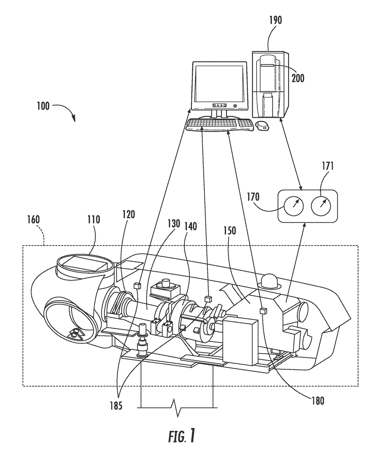
[0019]Reference now will be made in detail to embodiments of the invention, one or more examples of which are illustrated in the drawings. Each example is provided by way of explanation of the invention, not limitation of the invention. In fact, it will be apparent to those skilled in the art that various modifications and variations can be made in the present invention without departing from the scope or spirit of the invention. For instance, features illustrated or described as part of one embodiment can be used with another embodiment to yield a still further embodiment. Thus, it is intended that the present invention covers such modifications and variations as come within the scope of the appended claims and their equivalents.

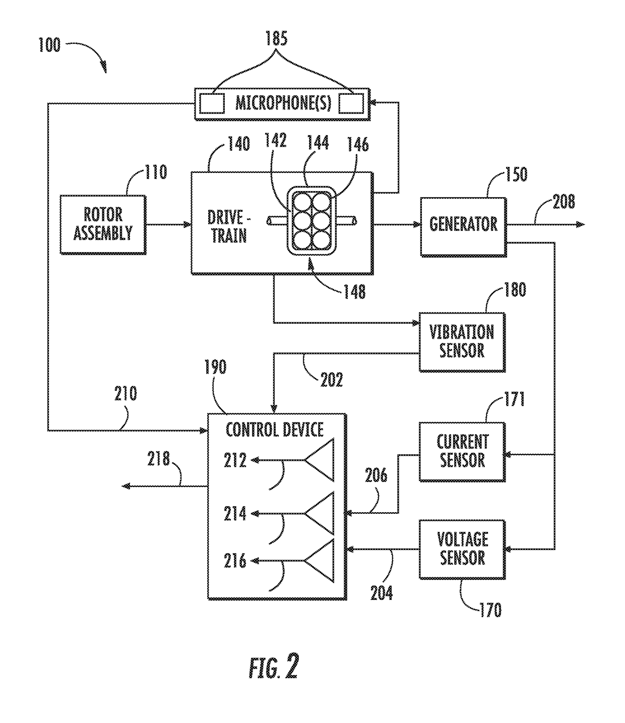
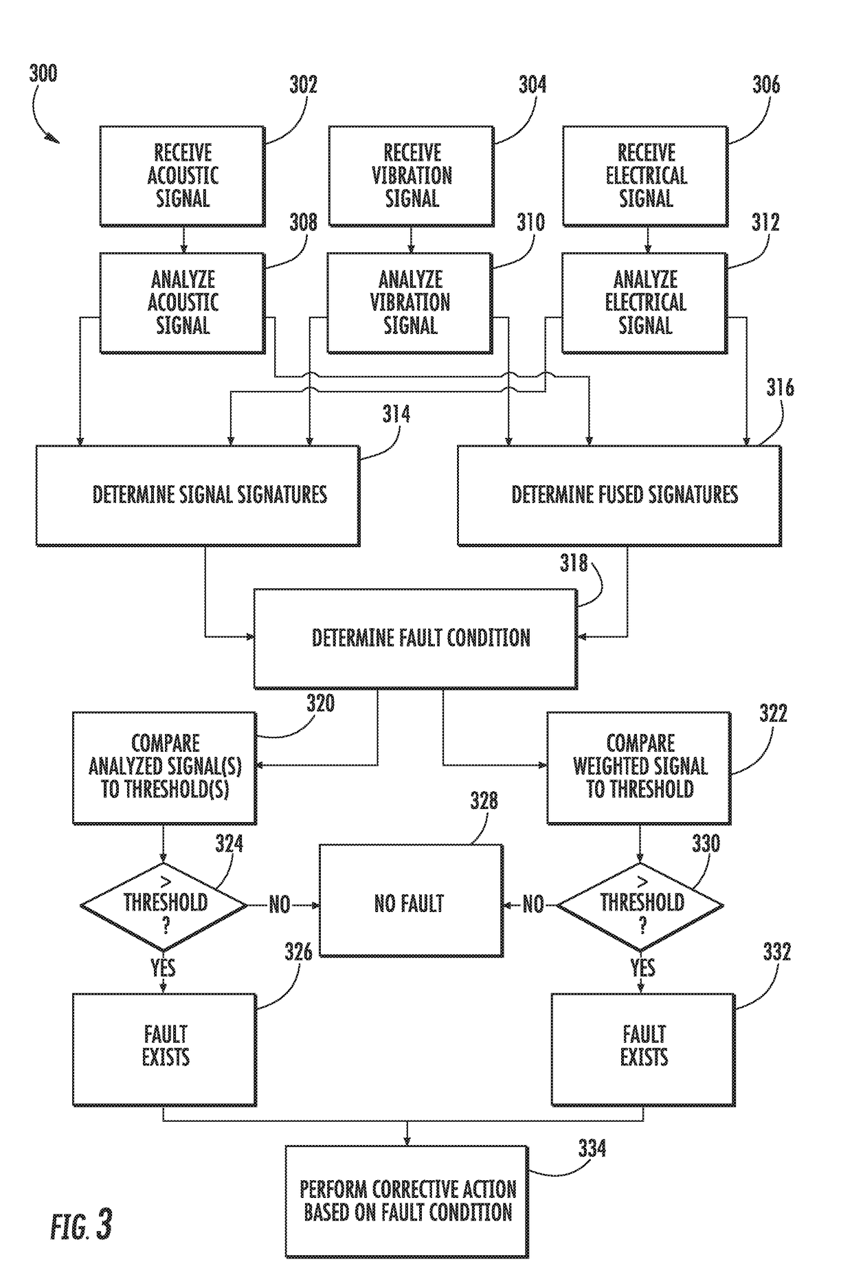
[0020]Generally, example aspects of the present disclosure are directed to systems and methods for detecting fault conditions. More particularly, a wind turbine system can include a drivetrain, which can include a plurality of components, such as gears, bea...


PUM


Abstract

Systems and methods for detecting faults are provided. A method for determining a fault condition for a component of a drivetrain in a wind turbine can include receiving an acoustic signal from an acoustic signal measuring device. The method can further include receiving a vibration signal from a vibration signal measuring device. The method can further include analyzing the acoustic signal to determine an analyzed acoustic signal. The method can further include analyzing the vibration signal to determine an analyzed vibration signal. The method can further include determining a fault condition for the component based at least in part on the analyzed acoustic signal and analyzed vibration signal. The fault condition can further be determined based at least in part on an analyzed electrical signal.

Description

GOVERNMENT SUPPORT CLAUSE[0001]This invention was made with Government support under Contract No. DE-EE0006802, awarded by the Department of Energy. The Government has certain rights in the invention.FIELD[0002]The present disclosure relates generally to wind turbines, and more particularly to methods and systems for improved detection of faults in various components of drivetrains in wind turbines.BACKGROUND[0003]Generally, a wind turbine includes a rotor that includes a rotatable hub assembly having multiple blades. The blades transform wind energy into a mechanical rotational torque that in turn drives a drivetrain coupled to an electrical generator. However, electrical generators, motors and the drive train in a wind turbine may generate torsional and radial vibrations due to presence of defective components such as bearings, gears, or the like. Conventionally, vibration analysis of components in a wind turbine can be performed to monitor operating conditions. For example, mecha...

Claims


Application Information

Patent Timeline
Patent Type & Authority Applications(United States)
IPC IPC(8): G01R31/34G01H1/00G01H15/00
CPCG01R31/343G01R31/346G01H1/006F05B2270/334F03D7/0296F03D17/00G01H15/00G01H1/003G01H3/12F05B2270/333G01R31/34Y02E10/72
Inventor UNNIKRISHNAN, JAYAKRISHNANHE, LIJUNMATTHEWS, BRETT ALEXANDERHAO, LIWEI
Owner GENERAL ELECTRIC CO
Learn More