
Pneumatic Tire

Inactive Publication Date: 2018-12-06
YOKOHAMA RUBBER CO LTD +1
View PDF2 Cites 1 Cited by
  • Summary
  • Abstract
  • Description
  • Claims
  • Application Information

AI Technical Summary

Benefits of technology

The patent text describes a pneumatic tire that can help reduce external noise and prevent the tire from getting damaged from water splashes.

Problems solved by technology

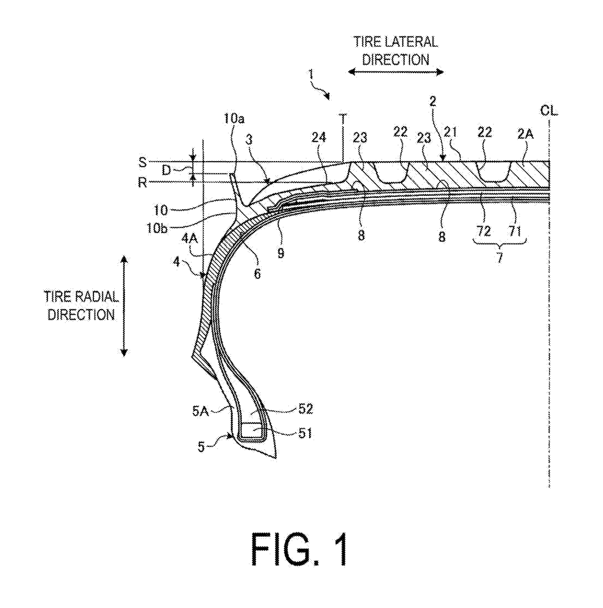
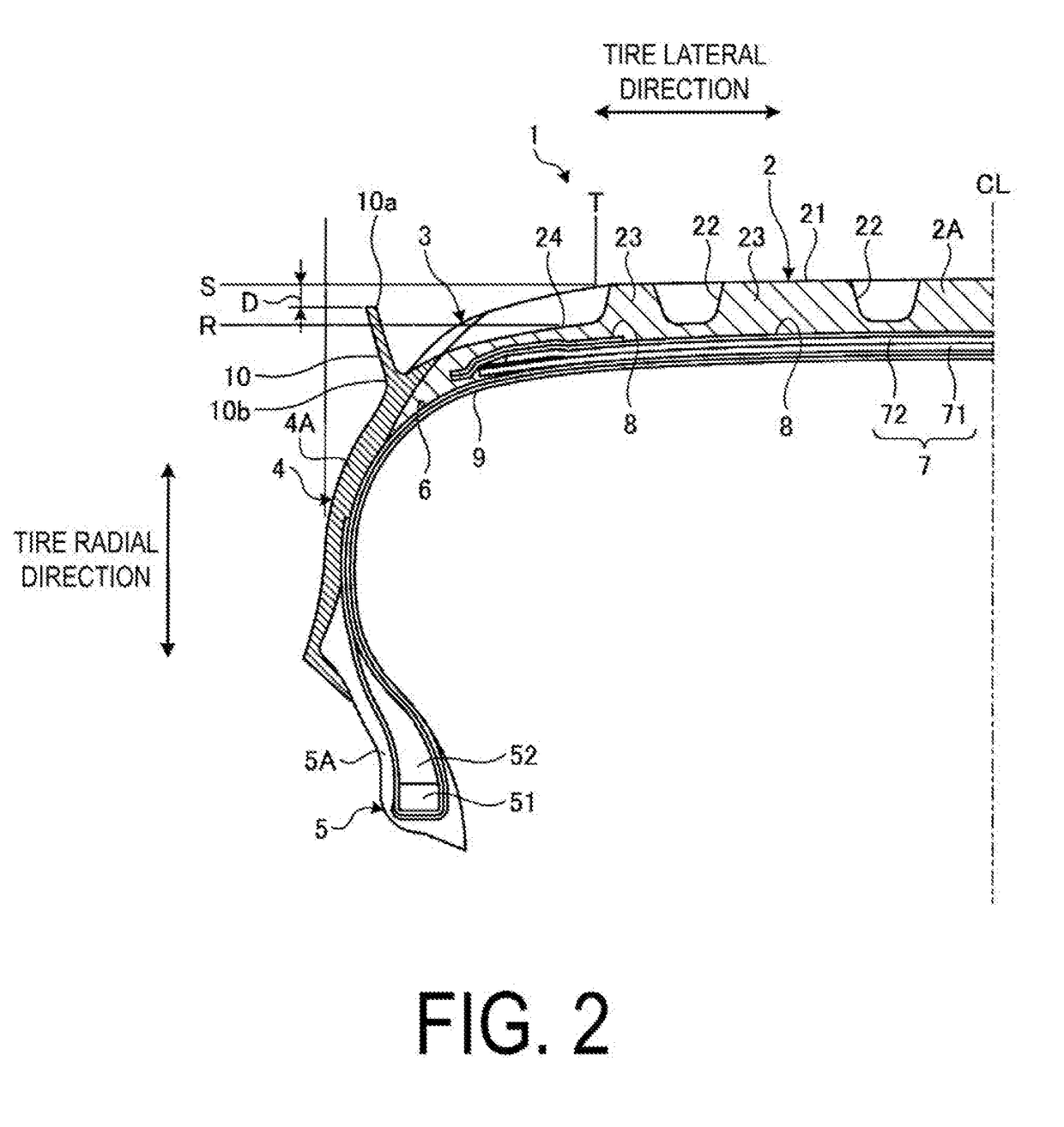
However, when the pneumatic tire rolls, the pneumatic tire deforms as it comes into contact with the ground, causing the projection portion to deform inward in the tire lateral direction.
Also, the opening portion outward of the lug groove in the tire lateral direction is blocked, and thus water resistance and hydroplaning resistance performance may be reduced.
As a result, the projection portion which deforms inward in the tire lateral direction becomes difficult to support, and the effect of ensuring a vehicle exterior noise reduction effect and hydroplaning resistance performance is decreased.
As a result, drainage properties decrease, and the effect of ensuring hydroplaning resistance performance is decreased.
As a result, the effect of ensuring a vehicle exterior noise reduction effect and hydroplaning resistance performance is likely to decrease.
When the total dimension of the stopper portions in the tire circumferential direction is less than 10% of the total dimension between the lug grooves in the tire circumferential direction, the projection portion which deforms inward in the tire lateral direction becomes difficult to support via the stopper portion.
As a result, the effect of ensuring a vehicle exterior noise reduction effect and hydroplaning resistance performance is likely to decrease.
When the angle formed by the center straight line and the tire radial direction line is greater than 15° inward in the tire lateral direction, the projection portion is susceptible to coming into contact with the tire itself, which may cause wear and chipping in the portion where contact occurs.
When the angle formed by the center straight line and the tire radial direction line is greater than 45° outward in the tire lateral direction, the projection portion is disposed away from the lug groove, and a noise shielding effect is difficult to obtain.

Method used


Image

  • Pneumatic Tire
  • Pneumatic Tire
  • Pneumatic Tire

Examples


examples

[0082]In the examples, performance tests for pass-by noise and hydroplaning resistance performance were performed on a plurality of types of pneumatic tires of different conditions (see FIGS. 16 and 17).

[0083]In the performance tests, pneumatic tires (test tires) having a tire size of 245 / 40R18 93W were mounted on regular rims (18×8 1 / 2J) and inflated to the regular internal pressure (250 kPa). Then, the pneumatic tires were mounted on a sedan type test vehicle having an engine displacement of 3000 cc.

[0084]In the evaluation method of pass-by noise, the magnitude of vehicle external pass-by noise was measured according to the tire noise test method specified in ECE Regulation No. 117 Revision 2 (ECE R117-02). In the test, the test vehicle was driven in a section prior to a noise measurement section, and before the noise measurement section, the engine was stopped and the test vehicle was allowed to coast in the noise measurement section where the maximum noise level dB (noise level ...


PUM


Abstract

A pneumatic tire comprises a lug groove disposed outermost in a tire lateral direction in a tread portion, the lug groove opening outward in the tire lateral direction; a projection portion disposed outward of an opening portion of the lug groove in the tire lateral direction, the projection portion extending outward in a tire radial direction past a groove bottom of the lug groove at maximum groove depth and comprising an end disposed inward of a road contact surface of the tread portion in the tire radial direction, when the pneumatic tire is mounted on a regular rim, inflated to a regular internal pressure, and loaded with 70% of a regular load; and a stopper portion projecting from a surface of the tread portion at a position outward of a ground contact edge in the tire lateral direction and inward of the projection portion in the tire lateral direction.

Description

TECHNICAL FIELD[0001]The present technology relates to a pneumatic tire that reduces external noise.BACKGROUND ART[0002]Pneumatic tires designed to reduce vehicle external noise are known. For example, the pneumatic tire described in Japanese Unexamined Patent Publication No. 2012-096776 includes a lug groove that opens outward in a tire lateral direction on an outermost side of a tread portion in the tire lateral direction, and a projection portion disposed outward of the opening portion of the lug groove in the tire lateral direction. According to this pneumatic tire, by the projection portion being located outward of the opening portion of the lug groove in the tire lateral direction, when a vehicle on which the pneumatic tire is mounted travels, the sound produced by air column resonance is prevented from being released outward from the lug groove in the tire lateral direction. As a result, vehicle external noise can be reduced.[0003]In another example, the pneumatic tire descri...

Claims


Application Information

Patent Timeline
IPC IPC(8): B60C11/01B60C13/00
CPCB60C11/01B60C13/00B60C13/02
Inventor HATA, HIROSHIMATSUDA, JUNKIM, KEE WOONPARK, CHANG JUNG
Owner YOKOHAMA RUBBER CO LTD
Learn More