
Pneumatic Actuation Systems Having Improved Feedback Control

a pneumatic actuation system and feedback control technology, applied in the direction of servomotor parallel arrangement, servomotor, power amplification, etc., can solve the problems of low use of the extensive control theory available for robust controller design, inconvenient operation, and inability to fully control the control system

Active Publication Date: 2018-11-29
AURORA FLIGHT SCI CORP
View PDF1 Cites 9 Cited by
  • Summary
  • Abstract
  • Description
  • Claims
  • Application Information

AI Technical Summary

Benefits of technology

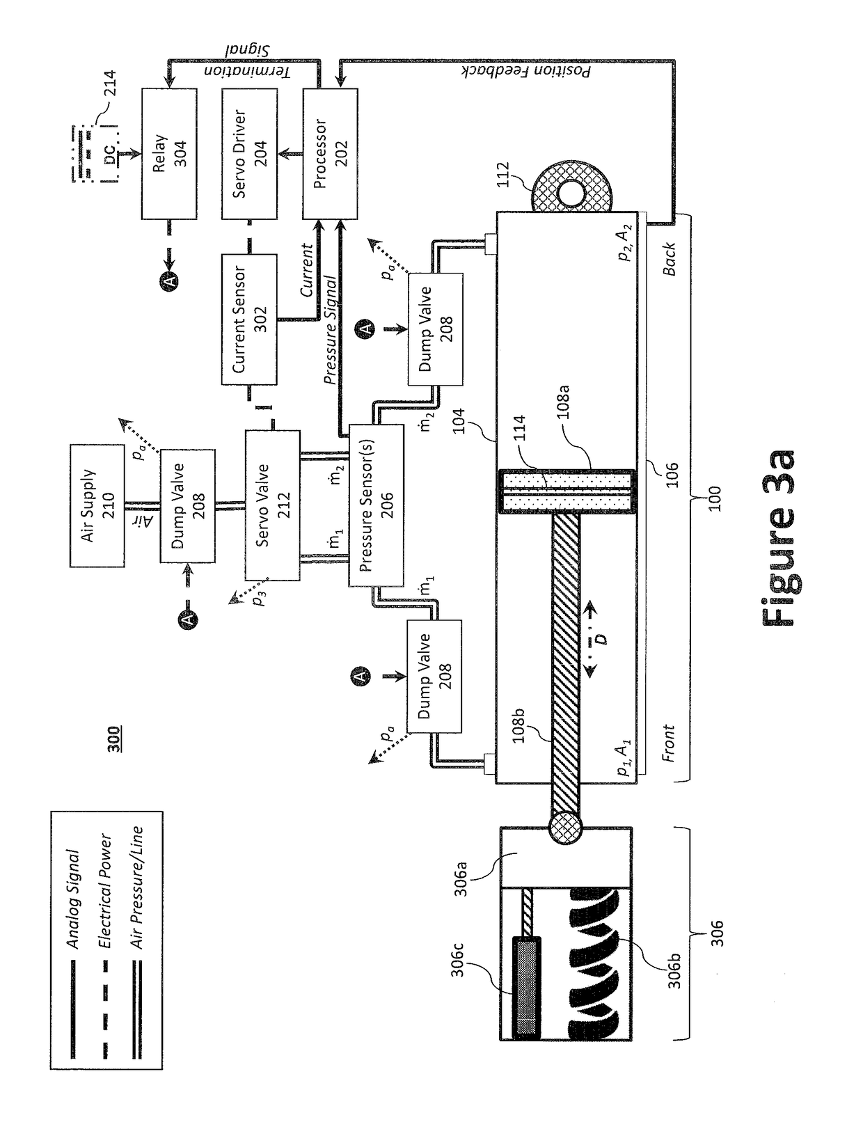
The present invention is a pneumatic actuation controller design that uses force feedback to provide a robust controller design. The invention includes a triplex pneumatic architecture system with three pneumatic subsystems that control movement of three pistons in three pneumatic actuation assemblies. Each subsystem includes a current sensor, a servo driver, a servo valve, a relay, and a processor to communicate a control command to the servo driver. The system also includes a communication bus to connect each subsystem and a processor to generate a termination signal to actuate the relay when the current sensor value deviates from the control command by a predetermined error value. The technical effect of the invention is a more reliable and accurate control of pneumatic actuation assemblies.

Problems solved by technology

Despite mechanical simplicity, the dynamics of pneumatic actuation systems are intrinsically non-linear because of the switching nature of pressure-control valves and non-linear nature of the airflow that governs pressure change in the cylinder itself.
That is, there is little use of the extensive control theory available for robust design of the controller.
In these implementations, some signals are used for system feedback, but the gain-selection or control-design process is still based largely on heuristics and / or experimentation, which can be expensive, inaccurate, and overly complicated.

Method used


Image

  • Pneumatic Actuation Systems Having Improved Feedback Control
  • Pneumatic Actuation Systems Having Improved Feedback Control
  • Pneumatic Actuation Systems Having Improved Feedback Control

Examples


Embodiment Construction

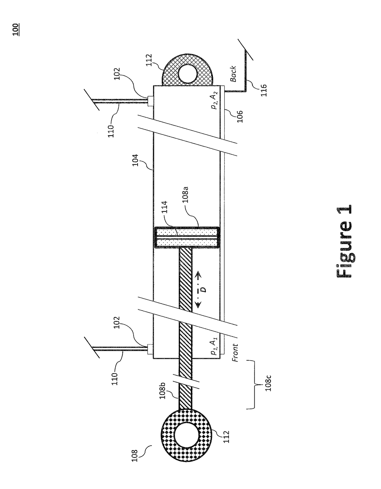
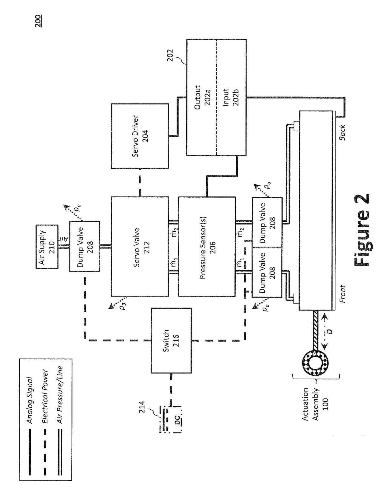
[0051]Preferred embodiments of the present invention will be described hereinbelow with reference to the accompanying drawings. The components in the drawings are not necessarily drawn to scale, the emphasis instead being placed upon clearly illustrating the principles of the present embodiments. For instance, the size of an element may be exaggerated for clarity and convenience of description. Moreover, wherever possible, the same reference numbers are used throughout the drawings to refer to the same or like elements of an embodiment. In the following description, well-known functions or constructions are not described in detail because they may obscure the invention in unnecessary detail. No language in the specification should be construed as indicating any unclaimed element as essential to the practice of the embodiments. In the following description, it is understood that terms such as “first,”“second,”“top,”“bottom,”“side,”“front,”“back,” and the like, are words of convenienc...


PUM


Abstract

A triplex pneumatic architecture system is disclosed having first, second, and third pneumatic subsystems where triplex redundancy may be accomplished by measuring only one particular node in each system, such as a measured current of the servo valve. Each of the first, second, and third pneumatic subsystems are configured to control a separate redundant pneumatic actuation assembly. Each subsystem may comprise a current sensor to measure a control current from a servo driver to a servo valve that controls the pneumatic actuation assembly to output a measured current value, and a dump valve coupled to a relay. Each processor is configured to generate a termination signal to actuate the first relay to open the first dump valve. The triplex pneumatic architecture system further includes a communication bus to communicatively couple each of the first, second, and third pneumatic subsystems. Each processor is configured to generate the termination signal and to communicate the termination signal to one or more of the relays when one measured current value deviates from the two other measured current values by a predetermined error value.

Description

STATEMENT OF GOVERNMENT INTEREST[0001]This invention was made with government support under Contract Number: HR0011-15-0027 awarded by the Defense Advanced Research Projects Agency (DARPA). The government has certain rights in the invention.TECHNICAL FIELD[0002]The present invention relates to a pneumatic actuation system, more particularly, to a triplex architecture for pneumatic actuation systems employing feedback compensation techniques.BACKGROUND[0003]Pneumatic actuation systems, which generally comprise a piston controlled by one or more pressure-control valves, are used in certain industrial applications. Recently, Aurora Flight Sciences Corporation (“Aurora”) of Manassas, Va. incorporated pneumatic actuation systems into aircraft control systems. For example, Aurora recently developed a right-seat pilot assistant capable of operating an aircraft during takeoff, cruise, and landing using pneumatic actuation to manipulate primary flight controls. Despite mechanical simplicity,...

Claims


Application Information

Patent Timeline
IPC IPC(8): F15B9/09F15B13/16F15B18/00F15B13/02F15B21/08F15B21/04F15B21/044
CPCF15B9/09F15B13/16F15B18/00F15B13/02F15B21/085F15B21/044B64C13/42B64C13/48F15B21/087F15B19/005F15B20/00
Inventor HUTCHISON, MATTHEW G.BOSWORTH, WILLIAMKEHLENBECK, ANDREWJENSEN, DEVIN
Owner AURORA FLIGHT SCI CORP
Learn More