Traceroutes for discovering the network path of inbound packets transmitted from a specified network node

Active Publication Date: 2018-11-22
AKAMAI TECH INC
View PDF3 Cites 16 Cited by
  • Summary
  • Abstract
  • Description
  • Claims
  • Application Information

AI Technical Summary

Benefits of technology

The patent text describes a technique for discovering the topology of computer networks using a reverse traceroute approach. This involves transmitting packets with a set of packets to a receiver, where the packets have a decreasing TTL value (the time it takes for the packet to reach its destination) in a way that allows the receiver to identify the network path taken by the packets. The conventional traceroute approach can only provide information on the forward network path from the sender to the receiver. However, this reverse traceroute technique allows the receiver to have more complete information about the transit paths between the two nodes. The invention also discusses the use of GRE tunnels for reverse traceroutes and the configuration of a distributed computer system as a content delivery network. The technical effects of the patent text include improved network topology understanding and improved bidirectional path reporting for reverse tracerouts.

Problems solved by technology

However, the conventional traceroute approach provide information only on a forward (outbound) network path for packets going from node A to B. The path taken by inbound packets sent from B to A is not known to A. Those paths may differ, i.e., network paths are not always symmetrical.
Of course, for node A to obtain information about the inbound network path from B to A, node B could perform a traceroute and send the results to A. But, in many circumstances this is impractical or inefficient, as it requires coordination between the entities operating A and B. A goal of the techniques herein is to enable node A to obtain inbound network path information about packets sent to A from B, preferably without node B performing a traceroute, and preferably without node B performing any testing reporting back to A.

Method used


Image

  • Traceroutes for discovering the network path of inbound packets transmitted from a specified network node
  • Traceroutes for discovering the network path of inbound packets transmitted from a specified network node
  • Traceroutes for discovering the network path of inbound packets transmitted from a specified network node

Examples


Embodiment Construction

[0015]The following description sets forth embodiments of the invention to provide an overall understanding of the principles of the structure, function, manufacture, and use of the methods, systems, and apparatus disclosed herein. The systems, methods and apparatus described in this application and illustrated in the accompanying drawings are non-limiting examples; the claims alone define the scope of protection that is sought. The features described or illustrated in connection with one exemplary embodiment may be combined with the features of other embodiments. Such modifications and variations are intended to be included within the scope of the present invention. All patents, patent application publications, other publications, and references cited anywhere in this document are expressly incorporated herein by reference in their entirety and for all purposes. The term “e.g.” used throughout is used as an abbreviation for the non-limiting phrase “for example.”

[0016]In one embodim...


PUM


Abstract

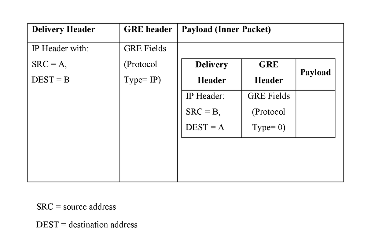
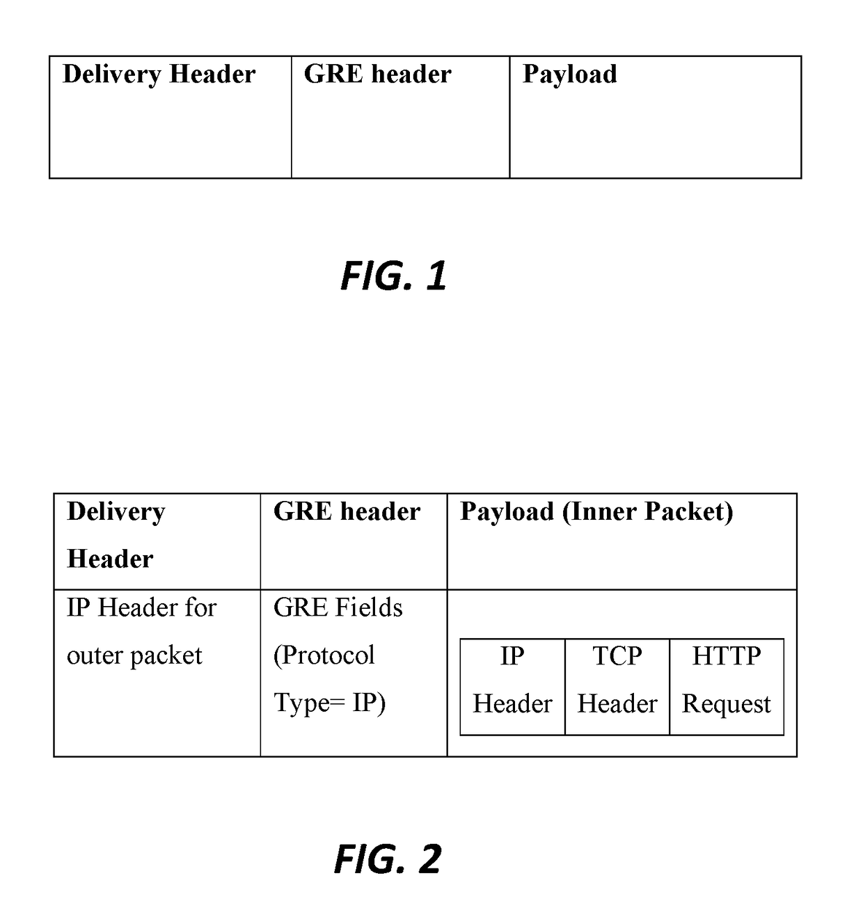
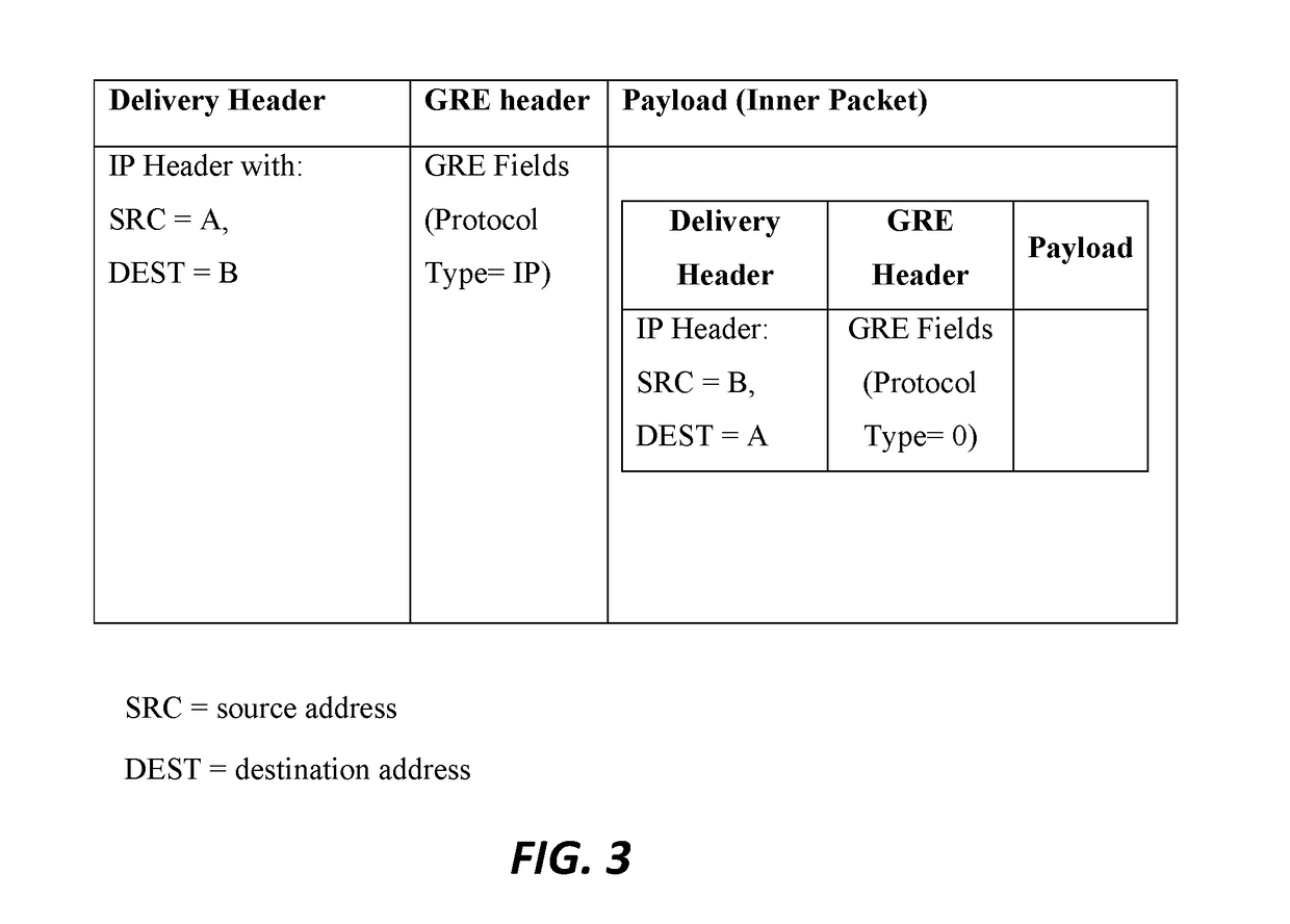
Disclosed herein are systems, methods, and apparatus for performing a new kind of traceroute. This traceroute is referred to herein as a “reverse” traceroute, as it enables a given network node to determine the path of packets sent to it from another node. Preferably, an encapsulating tunnel between the two nodes is leveraged. Preferably, a given network node (“first node”) performs the reverse traceroute by sending encapsulated inner packets in the tunnel to another network node (“second node”). The second node reflects the inner packets back to the first node. Preferably, the inner packets are configured such that their IP header TTLs expire at intermediate nodes (such as routers), and such that the resulting error messages are reported to the first node. In this way, the first node obtains information about the topology of the network and the path taken by inbound packets.

Description

BACKGROUNDTechnical Field[0001]This patent document relates generally to computer networking and to techniques for discovering the topology of computer networks.Brief Description of Background Art[0002]Traceroute is a well-known technique for discovering network topology between a sender and receiver. In brief, a traceroute involves a network node (referred to here as node A) transmitting a set of packets to another network node (referred to here as node B). The set of packets are configured such that the TTL value in the IP packet header is incrementally increased (or varied) across successive packets. For example, the first packet has TTL=N, the next packet has TTL=N+1, the next packet has TTL=N+2, and so on. The TTL is essentially a permissible hop count for the packet. Routers along the network path will examine the TTL field of packets they receive before forwarding them. Routers decrement the TTL of a given packet by one before forwarding it. If a router finds that the TTL wil...

Claims


Application Information

Patent Timeline
IPC IPC(8): H04L12/26H04L12/46H04L12/733H04L45/122
CPCH04L43/062H04L2212/00H04L45/20H04L12/4633H04L43/06H04L43/10H04L41/12
Inventor BRISTOW, PETER
Owner AKAMAI TECH INC
Why Eureka
Try Eureka