
Wireless power receiving device, wireless power supply device, wireless power transmission system, and method for protecting wireless power receiving device from excessive magnetic field

Active Publication Date: 2018-11-22
LAPIS SEMICON CO LTD
View PDF0 Cites 15 Cited by
  • Summary
  • Abstract
  • Description
  • Claims
  • Application Information

AI Technical Summary

Benefits of technology

This patent provides a solution for protecting wireless devices from excessive magnetic field during power transmission. The invention provides a wireless power receiving device that can protect itself from excessive magnetic field while also minimizing electric power loss. The patent also describes a wireless power supply device and a wireless power transmission system that can effectively prevent excessive magnetic field while ensuring low electric power loss.

Problems solved by technology

In this case, due to the strong magnetic field generated by the power transmission device, the IC card receiving the strong magnetic field generates heat beyond necessity and may be damaged.
However, in the abovementioned non-contact electric power transmission device, in order to detect the current flowing through the power transmission coil, a current sensor is arranged in series between a power-supply line and a power transmission circuit, so that electric power loss is generated in the current sensor itself.

Method used


Image

  • Wireless power receiving device, wireless power supply device, wireless power transmission system, and method for protecting wireless power receiving device from excessive magnetic field
  • Wireless power receiving device, wireless power supply device, wireless power transmission system, and method for protecting wireless power receiving device from excessive magnetic field
  • Wireless power receiving device, wireless power supply device, wireless power transmission system, and method for protecting wireless power receiving device from excessive magnetic field

Examples


Embodiment Construction

[0038]In the following unit, embodiments of the disclosure are described in detail with reference to the drawings.

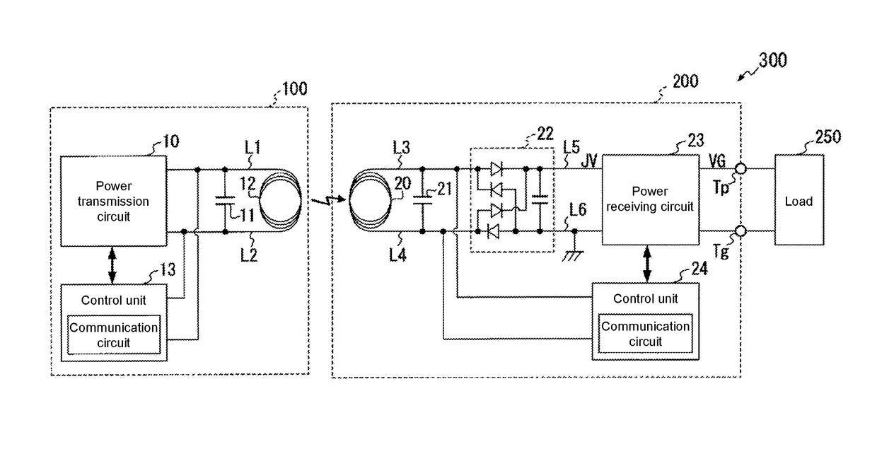
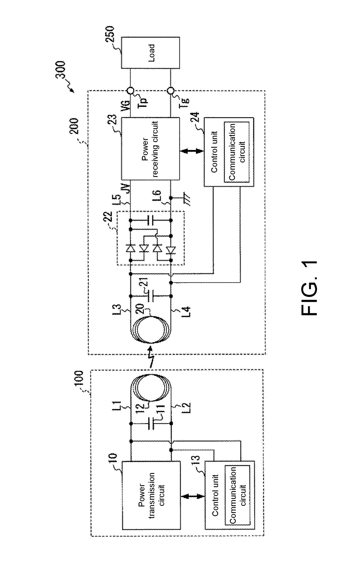
[0039]FIG. 1 is a block diagram showing a schematic structure of a wireless power transmission system 300, which includes a wireless power supply device 100 and a wireless power receiving device 200 of the disclosure, and a load device 250 that receives the supply of an output voltage acting as a power-supply voltage from the wireless power receiving device 200.

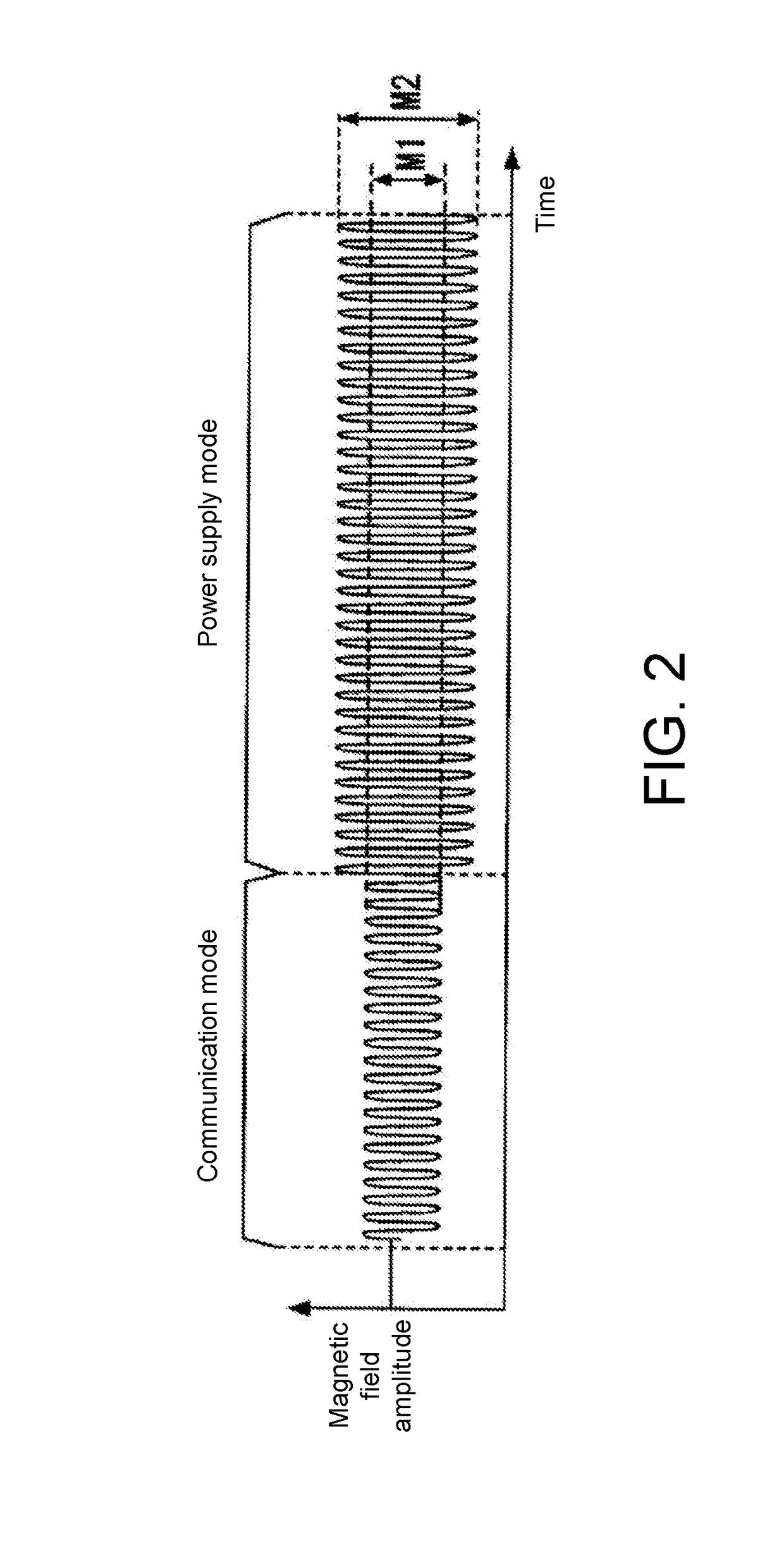
[0040]In the wireless power transmission system 300, a power supply mode in which power supply is performed from the wireless power supply device 100 to the wireless power receiving device 200 by an alternative magnetic field, and a communication mode in which data communication is performed between the wireless power supply device 100 and the wireless power receiving device 200 by the alternative magnetic field are performed in a time division manner.

[0041]In the following unit, internal structures of the wireles...


PUM


Abstract

The disclosure provides a wireless power receiving device, a wireless power supply device, and a wireless power transmission system. The wireless power receiving device includes: a conversion unit that converts an alternative magnetic field into a reception voltage that has a voltage value corresponding to an amplitude of the alternative magnetic field; a power receiving circuit that generates a stabilized voltage with a fixed voltage value based on the reception voltage, and outputs an output voltage corresponding to the stabilized voltage via an output line; and a communication circuit that receives the stabilized voltage as a power-supply voltage to perform the data communication; the power receiving circuit includes a protection circuit that restricts an upper limit of the reception voltage to a first voltage value in the communication mode, and restricts the upper limit to a second voltage value higher than the first voltage value in the power supply mode.

Description

CROSS-REFERENCE TO RELATED APPLICATION[0001]This application claims the benefit of Japan Application no. 2017-097424, filed on May 16, 2017. The entirety of the above-mentioned patent application is hereby incorporated by reference herein and made a part of this specification.BACKGROUND1. Technical Field[0002]The disclosure relates to a wireless power supply device which supplies electric power without contact, a wireless power receiving device which receives supply of electric power without contact, a wireless power transmission system including the wireless power supply device and the wireless power receiving device, and a method for protecting the wireless power receiving device from an excessive magnetic field.2. Description of Related Art[0003]In recent years, a wireless power transmission system, which wirelessly supplies electric power to a wearable apparatus such as a clock or an IC (Integrated Circuit) card by using an alternative magnetic field, has been commercialized. Th...

Claims


Application Information

Patent Timeline
IPC IPC(8): H02H9/04H02J50/12H02H1/00H02M7/06G05F1/575H02J50/60
CPCH02H9/04H02J50/12H02H1/0007H02M7/06G05F1/575H02J50/60H04B5/0037H02J50/80H02H3/08H02M3/33573H02M3/01H02M1/32H02M3/33523Y02B70/10H02M1/0009H02M1/0064H02M1/0058H04B5/79
Inventor TAYA, TAKASHI
Owner LAPIS SEMICON CO LTD
Learn More