Eureka AIR delivers breakthrough ideas for toughest innovation challenges, trusted by R&D personnel around the world.

Near-eye display with extended effective eyebox via eye tracking

a technology of eye tracking and eye display, applied in the field of eye display, can solve the problem of occlusion of at least a portion of the imagery intended to be displayed to the user's ey

Active Publication Date: 2018-11-15
GOOGLE LLC
View PDF3 Cites 19 Cited by
  • Summary
  • Abstract
  • Description
  • Claims
  • Application Information

AI Technical Summary

Benefits of technology

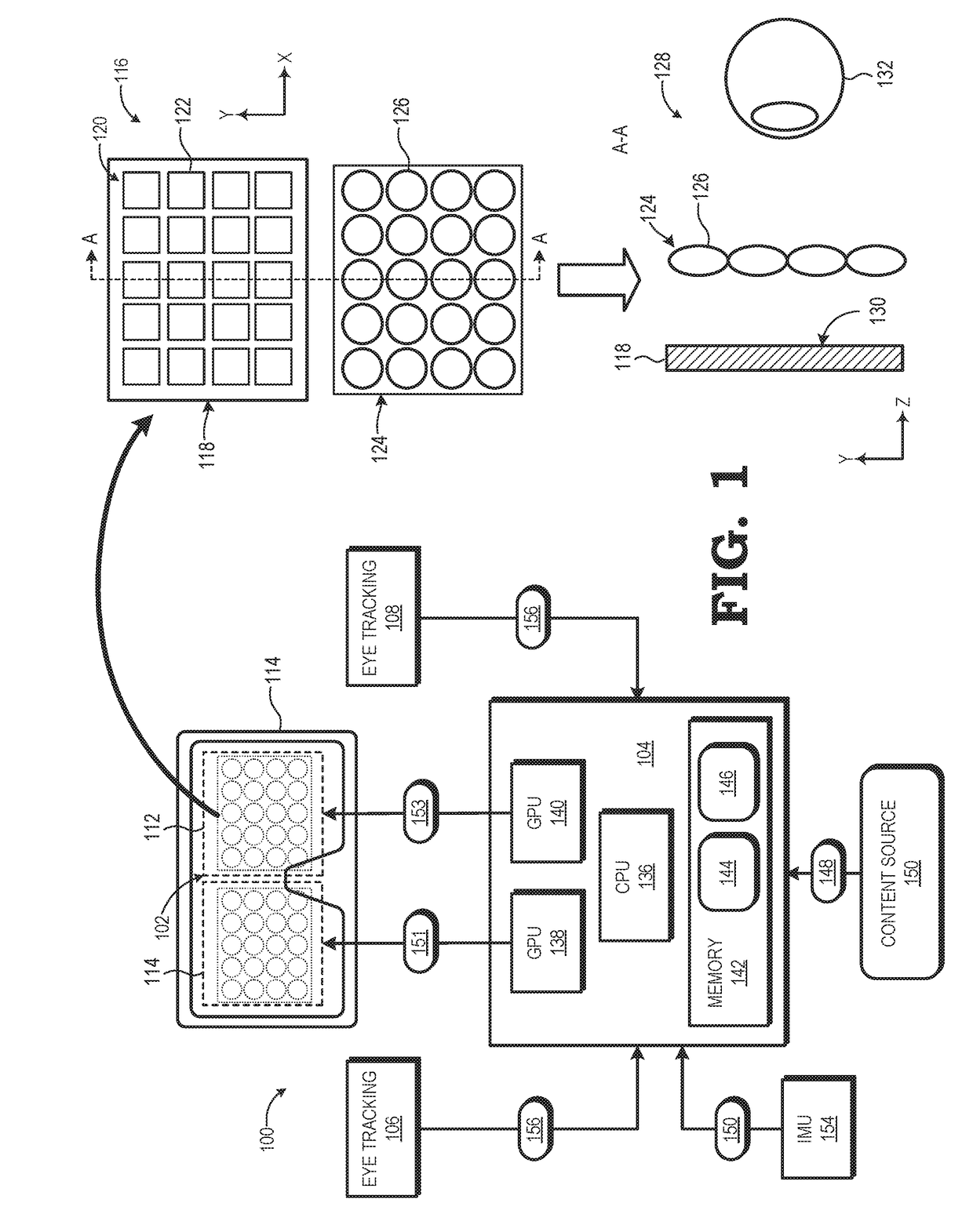
The present disclosure relates to improving the effective eye-box size in near-eye displays by adjusting the eyebox size based on the user's eye position and the accuracy of eye tracking. The technical effect of this is that it allows for a larger eyebox without compromising the field of view, providing a better user experience. The disclosed system uses eye tracking to determine the user's eye position and shifts the array of elemental images accordingly to effectively shift the eyebox of the display. This compensates for any deviation in the user's eye position, ensuring a comfortable viewing experience.

Problems solved by technology

Thus, to provide satisfactory FOV, a conventional near-eye display system employing an near-eye lightfield display typically has a relatively limited eyebox, which often is problematic in view of the variability of inter-pupillary distance (IPD) among the population of potential users and the variability in accurate positioning of a user's eye relative to the display, either of which can result in a user's pupil falling outside of the boundaries of the eyebox and thus resulting in occlusion of at least a portion of the imagery intended to be displayed to the user's eye.

Method used


Image

  • Near-eye display with extended effective eyebox via eye tracking
  • Near-eye display with extended effective eyebox via eye tracking
  • Near-eye display with extended effective eyebox via eye tracking

Examples


Embodiment Construction

[0013]FIGS. 1-9 illustrate example methods and systems for dynamic eyebox adjustment based on user eye pose in a near-eye display system. In at least one embodiment, the near-eye display system employs a computational display to display near-eye lightfield frames of imagery to a user so as to provide the user with an immersive virtual reality (VR) or augmented reality (AR) experience. Each near-eye lightfield frame is composed of an array of elemental images, with each elemental image representing a view of an object or scene from a different corresponding viewpoint. An array of lenslets overlies the display panel and operates to present the array of elemental images to the user as a single autostereoscopic image.

[0014]As the eyebox dimensions, or “size”, for the computational display are proportional to the ratio of eye relief to lenslet focal length, an attempt to increase eyebox size generally results in reduced field of view (FOV), and vice versa. To provide improved eyebox size...


PUM


Abstract

A near-eye display system includes a display panel to display a near-eye lightfield frame comprising an array of elemental images and an eye tracking component to track a pose of a user's eye. The system further includes a rendering component to position the array of elemental images within the near-eye lightfield frame based on the pose of the user's eye. A method of operation of the near-eye display system includes determining, using the eye tracking component, a first pose of the user's eye and determining a shift vector for an array of elemental images forming a near-eye lightfield frame based on the first pose of the user's eye. The method further includes rendering the array of elemental images at a position within the near-eye lightfield frame that is based on the shift vector.

Description

BACKGROUNDField of the Disclosure[0001]The present disclosure relates generally to near-eye displays and, more particularly, to improvement of effective eye-box size in near-eye displays.Description of the Related Art[0002]Head-mounted displays (HMDs) and other near-eye display systems can utilize a near-eye lightfield display or other computational display to provide effective display of three-dimensional (3D) graphics. Generally, the near-eye lightfield display employs one or more display panels and an array of lenslets, pinholes, or other optic features that overlie the one or more display panels. A rendering system renders an array of elemental images, with each elemental image representing an image or view of an object or scene from a corresponding perspective or virtual camera position. Such near-eye lightfield displays typically exhibit a tradeoff between eyebox size and field of view (FOV) as eyebox size is proportional to the ratio of eye relief to lenslet focal length. Thu...

Claims


Application Information

Patent Timeline
IPC IPC(8): G09G3/02G06T3/40G09G3/00G06T7/70G06T3/20
CPCG09G3/02G06T3/40G09G3/003H04N13/31G06T3/20G06T19/006H04N13/383G06T7/70G06F3/013G06T2207/20228G02B2027/0123G02B27/0172G02B27/0075H04N23/957H04N23/20H04N23/55H04N5/33
Inventor PERREAULT, JOHN D.LLULL, PATRICK
Owner GOOGLE LLC
Why Eureka
Eureka Blog
Learn More