Limb restraint

a technology for limbs and legs, applied in medical science, ambulance services, medical transportation, etc., can solve the problems of limiting the function of stretchers, limiting the use of limb restraint devices used in patient care, and time-consuming task of locating them

Active Publication Date: 2018-11-15
DAVES MEDICAL LLC
View PDF0 Cites 3 Cited by
  • Summary
  • Abstract
  • Description
  • Claims
  • Application Information

AI Technical Summary

Benefits of technology

[0022]The present invention relates to a novel limb restraint device and apparatus for storage onto an external object. More particularly, the invention relates to a device that is capable in making wrist or ankle restraints more readily available, sanitary and pre-attached or easily attached to an external structure or medical stretcher rail.

Problems solved by technology

Limb restraint devices used in connection with patient care are generally limited in use because they have no pre-determined connection points on which to apply to the stretcher and consequently are stored separate from the stretcher.
Because traditional limb restraint products are separate from stretchers, they are often stored in drawers and medical bags so locating them can be a time-consuming task.
While some limb restraints products on the market can be pre-connected or tied to the stretcher, doing so would possibly limit the stretcher functions because the restraint or restraints could interfere with day-to-day stretcher operation.
For example, you would have lengths of strap or Velcro that would be external of the stretcher dragging or possibly catching another object and further possibly blocking the folding of the side rails of the stretcher.
Furthermore, these restraints can become contaminated, as they are not protected from damage, or biological matter, vomit, blood, etc.
Another drawback is that traditional restraints need to be looped or tied to the external structure in order to be attached and are not designed to be pre-connected to the stretcher prior to a person needing to be restrained.
Having this design you must take both hands off patient or enlist the help of more providers, thereby increasing the chances of risk and delaying patient care.

Method used


Image

  • Limb restraint
  • Limb restraint
  • Limb restraint

Examples


Embodiment Construction

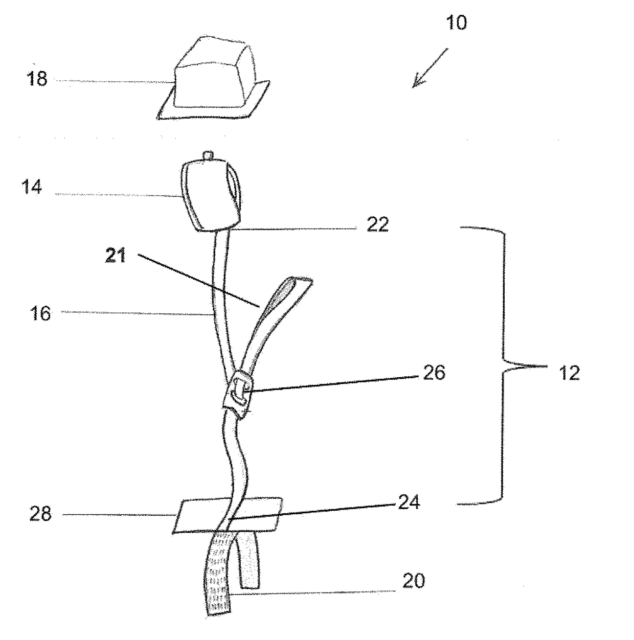
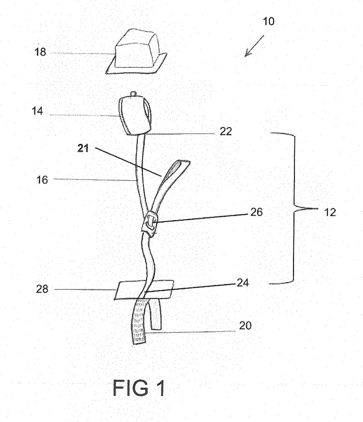
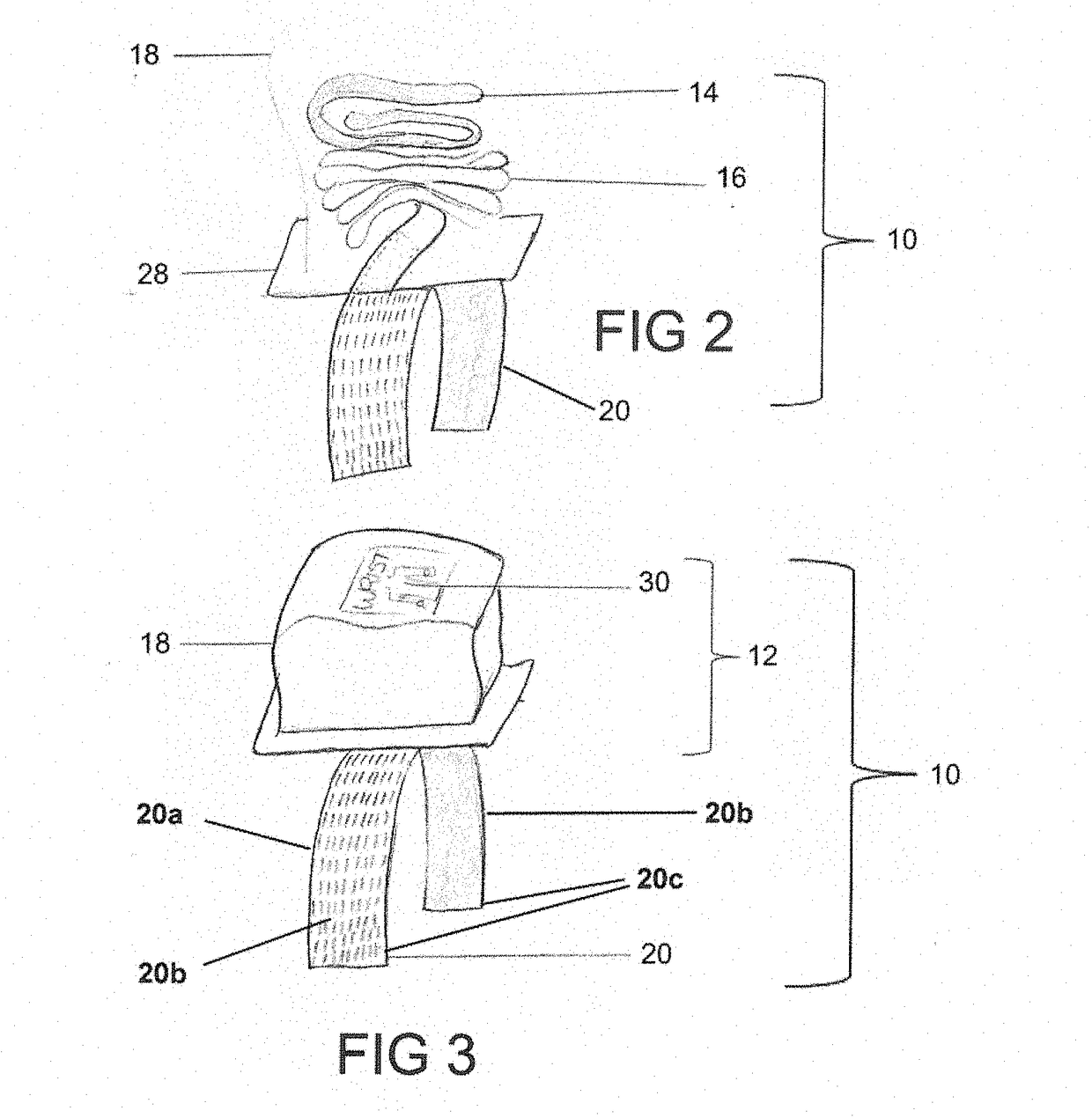
[0046]Referring to FIGS. 1-7, the numeral 10 generally designates a restraint system according to an embodiment of the present disclosure. As best seen in FIG. 1, restraint system 10 includes a restraint assembly 12, which includes a restraint cuff 14 (such as a wrist cuff or leg cuff), a tether 16, and a cover 18, and an anchor 20 to mount restraint assembly 12 to a person support apparatus, as noted, such as a patient support apparatus, including a cot, a stretcher, a bed, a chair, such as a wheelchair or a stair chair, or other patient transport apparatuses, including a back board as noted below. As will be more fully described below, cover 18 encloses cuff 14 and tether 16 (and optionally an adjustment mechanism) to protect them from bodily fluids and / or dirt and debris.

[0047]Tether 16 is coupled on one end to cuff 14, as noted by an optional coupler 22, and coupled at its other end to anchor 20, which as noted is configured to mount restraint assembly 12 to a person support app...


PUM


Abstract

A restraint system includes a restraint assembly and an anchor to releasably mount the restraint assembly to a component. The restraint assembly includes a tether and a cuff coupled to the tether. In addition, the restraint assembly includes a frangible cover operable to hold the tether and the cuff in a compact, stowed configuration and is sufficiently frangible to allow a person to tear open the cover. The tether is coupled to the anchor and when the cover is opened, the tether and the cuff are operable to be deployed from their stowed configuration, and the cuff extended from the anchor.

Description

[0001]This application claims the benefit of U.S. Prov. App. Ser. No. 62 / 503,821, filed by David Dufek, entitled LIMB RESTRAINT, on May 9, 2017, which is incorporated by reference herein in its entirety.BACKGROUND[0002]Medical limb restraints are used in connection with sedated, combative or agitated patients, to secure their wrists or ankles when emergency care is needed. When a patient is immobile, treatment can be administered safely and more effectively. These devices prevent patients from disrupting emergency treatment provided by healthcare providers in the field or hospital setting. Limb restraints prevent patients from dislodging various medical devices, such as endotracheal tubes, IV, or intravenous catheters, to name only a few.[0003]Limb restraint devices used in connection with patient care are generally limited in use because they have no pre-determined connection points on which to apply to the stretcher and consequently are stored separate from the stretcher. Because ...

Claims


Application Information

Patent Timeline
Patent Type & Authority Applications(United States)
IPC IPC(8): A61F5/37A61G1/044
CPCA61F5/3761A61G1/044A61F5/3769A61F5/3776A61F5/3792
Inventor DUFEK, DAVID A.
Owner DAVES MEDICAL LLC
Why Eureka
Try Eureka