Cutlery bundle securing assembly and method

a technology for securing assembly and cutlery, which is applied in the field of cuttinglery bundle holders, can solve problems such as the destruction of the loop, and achieve the effects of simple and inexpensive utensil bundles, simple, quick and intuitive, and easy tightening and loosening

Inactive Publication Date: 2018-11-15
NAPKIN KNOTS LLC
View PDF1 Cites 0 Cited by
  • Summary
  • Abstract
  • Description
  • Claims
  • Application Information

AI Technical Summary

Benefits of technology

[0013]It has been recognized that a simple and inexpensive utensil bundle securing solution can be configured using a string that is tied into a double string slip knot loop that can be easily tightened and loosened about a utensil bundle to secure and release the bundle in an simple, quick and intuitive fashion. The string length can be sufficient to accommodate various bundle dimensions and therefore can be used with different bundle assemblies for different events. To secure a bundle the loop is loosened, the bundle inserted lengthwise through the loop opening and one end of the loop is pulled to tighten the loop about a central or other section of the bundle until the loop applies a force against an outer circumferential surface of the bundle. The force of the bundle on the facing surface of the loop causes friction between the string knot and an engaged surface of the string so that the loop remains frictionally locked until affirmatively loosened by a user. In at least some cases the string used to form the loop may be formed of a material that causes high friction so that the string is maintained in the secure state until affirmatively loosened by a user. For instance, in some cases, at least the portions of the string that form the slip knot and that pass through the knot are formed by a waxed cotton cord so that slip knot friction is substantial. Here, again, once tightened in the securing position, the outward force applied by the bundle (e.g., a resilient napkin about a utensil stack) causes the frictional force of the knot to be sufficient to eliminate the possibility of inadvertent release.
[0014]In at least some cases, in addition to forming the slip knot, the string may form a stop knot at a second end of the string opposite the slip knot where the stop knot dimensions restrict the stop knot from passing through the slip knot. Thus, here, a user cannot inadvertently loosen the loop to the point where the second end of the string is pulled out of the slip knot so that the loop is destroyed.
[0016]In at least some cases, in addition to the string loop, the solution will also include a decorative label assembly attached to the string that can be more specially themed for specific events. For instance, in at least some cases a planar placard may be appended to the string loop where an exterior surface of the placard includes themed indicia that can be specialized for a specific event. In at least some cases the placard may be formed of a thick fibrous card stock to minimize solution costs. In other cases the placard may be formed of a thin plastic or otherwise substantially rigid material. While the placard may be glued to the string loop in some cases, in particularly advantageous cases a sticker may be applied to a rear surface of the placard with a portion of the string passing between the rear placard surface and the sticky surface of the sticker so that the placard is restrained from moving along the length of the string. In at least some cases the string may include one or more knots adjacent the location along the string length at which the placard is to be attached to help maintain the placard secured to the string. For instance, the sticker and placard may be centered on a central knot to increase friction between the placard, sticker and string. In some cases two or more centering knots may be formed on the loop for optimally locating the placard and for increasing robustness of the securing mechanism.

Problems solved by technology

Thus, here, a user cannot inadvertently loosen the loop to the point where the second end of the string is pulled out of the slip knot so that the loop is destroyed.

Method used


Image

  • Cutlery bundle securing assembly and method
  • Cutlery bundle securing assembly and method
  • Cutlery bundle securing assembly and method

Examples


Embodiment Construction

[0041]The various aspects of the subject disclosure are now described with reference to the drawings, wherein like reference numerals correspond to similar elements throughout the several views. It should be understood, however, that the drawings and detailed description hereafter relating thereto are not intended to limit the claimed subject matter to the particular form disclosed. Rather, the intention is to cover all modifications, equivalents, and alternatives falling within the spirit and scope of the claimed subject matter.

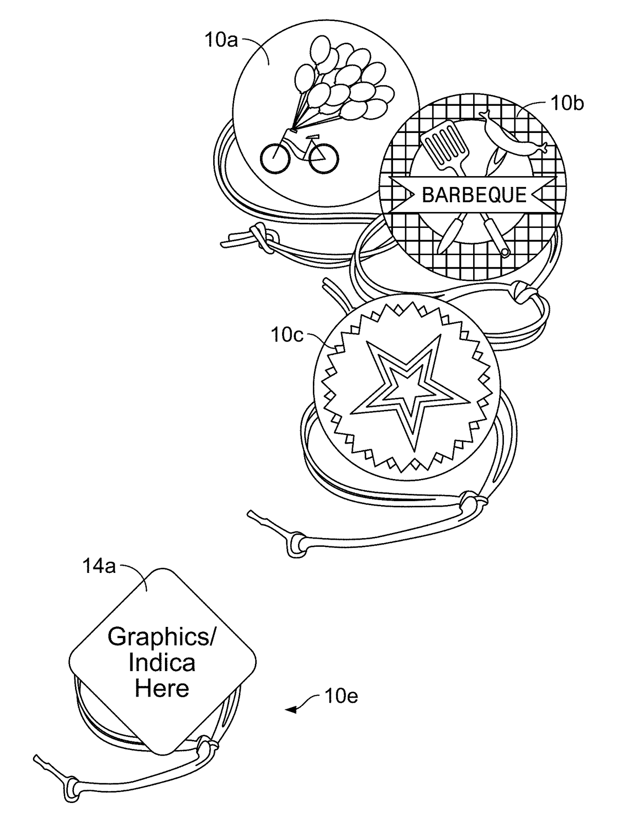
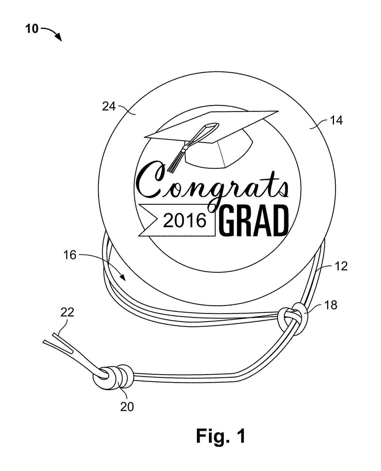
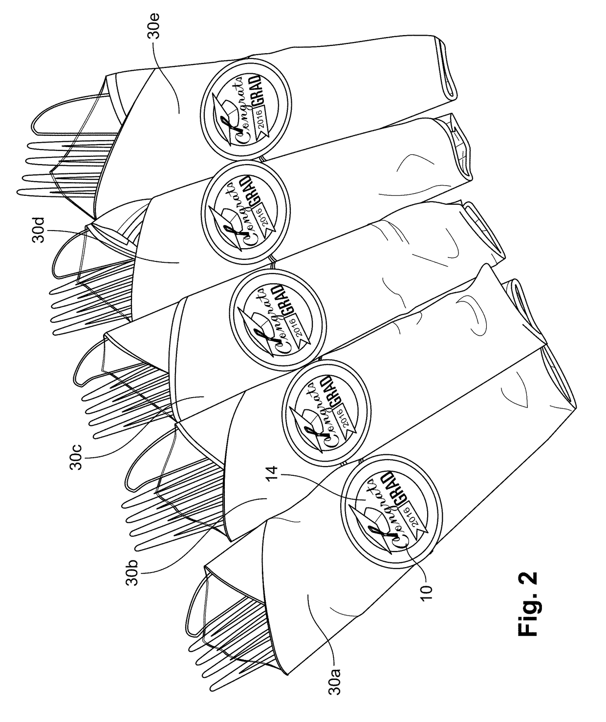
[0042]Referring now to the figures and more specifically to FIGS. 1 through 3, the present disclosure will be described in the context of an exemplary bundle securing solution 10 (10a-10e) that may be used to secure a utensil bundle as shown generally in FIG. 2. Referring also to FIGS. 4 and 5, an exemplary solution 10 includes a single binding strand 12, a placard 14 and a sticker 26. The strand 12 is arranged to form a plurality of knots that cause the str...


PUM


Abstract

A utensil bundle assembly comprising a single strand having a first end and a second end and an intermediate portion therebetween, the intermediate portion forming a single slip knot through which the first and second ends pass, strand portions adjacent the first and second ends moveable through the slip knot to different locations to adjust the dimension of a loop portion formed by the strand and a placard including a front surface and a rear surface, the placard mounted to the loop portion of the strand with the front surface exposed.

Description

CROSS-REFERENCE TO RELATED APPLICATIONS[0001]This application is a continuation of U.S. patent application Ser. No. 15 / 678,277 which was filed on Aug. 16, 2017 and which was titled “Cutlery Bundle Securing Assembly And Method” and also claims the benefit of U.S. Provisional Application No. 62 / 375,632 filed Aug. 16, 2016, all of which is incorporated herein by reference.STATEMENT REGARDING FEDERALLY SPONSORED RESEARCH OR DEVELOPMENT[0002]Not applicable.BACKGROUND OF THE DISCLOSURE[0003]The field of the disclosure is cutlery bundle holders and more specifically a mechanical assemblage for maintaining a napkin in a folded or bundled state.[0004]When people entertain guests at their homes or other locations, they often want to make events special and memorable. One way to make events special and memorable is by decorating event venues in unique ways that reflect the reason an event is held. For instance, people routinely decorate their homes for Christmas parties, Easter parties, gradua...

Claims


Application Information

Patent Timeline
Patent Type & Authority Applications(United States)
IPC IPC(8): A47G21/16A47G21/14
CPCA47G21/14A47G21/16
Inventor RYAN, TRACYDOUGHERTY, ANNIE
Owner NAPKIN KNOTS LLC
Why Eureka
Try Eureka