
Electronics equipment testing apparatus and method utilizing unintended RF emission features

a technology of unintended rf and testing apparatus, which is applied in the direction of waveguide horns, instruments, frequency measurement arrangements, etc., can solve the problems of inaccurate methods based on accumulated hours of operation, impending component or equipment failure, and saving premature replacement costs of equipmen

Active Publication Date: 2018-11-01
NOKOMIS
View PDF0 Cites 19 Cited by
  • Summary
  • Abstract
  • Description
  • Claims
  • Application Information

AI Technical Summary

Benefits of technology

The patent is about a system and method for detecting aging or degradation in electrical and electronic devices, particularly avionics equipment. The system and method use a non-intrusive approach to detect changes in the intended or unintended electromagnetic emissions given off by the devices, which can be caused by aging or degradation. The system and method can also detect components that may be inadequate or out-of-specification due to manufacturing variation or placement of obsolete or malfunctioning parts. The technical effects of the patent include improved accuracy in detecting impending component or equipment failures, saving premature replacement costs of equipment, and identifying equipment that still retains significant useful life. The patent also addresses the need for a non-intrusive way to test equipment mounted within racks, enclosures, or panels in vehicles such as planes, ships, submarines, automobiles, rockets, missiles, and trains.

Problems solved by technology

Conventionally, employed solutions to the problem of detecting aging in electronic devices and, particularly, avionics equipment can utilize methods which are inaccurate and are based on accumulated hours of operation.
These methods may not typically detect impending component or equipment failures which can occur before the equipment reaches the end of its Remaining Useful Life (RUL), nor it may detect equipment that, albeit is aged, still retains significant useful life, thus potentially saving premature replacement costs of equipment which is older by age but still has sufficient RUL.
This again can be inaccurate and typically requires additional equipment removal and testing events and higher net equipment costs than needed, and adds risk of premature failure(s).
Early replacement and unnecessary redundancy can squander thousands of hours of useful life still possible with good equipment while still allowing costly and potentially deadly failures to occur in unevenly stressed systems.
The above methods also do not address components that may be inadequate or out-of-specification due to manufacturing variation or the placement of obsolete, malfunctioning, or counterfeit parts and / or ICs placed in new systems, either accidentally or intentionally.
Further, the above methods may require an intrusive means, such as removal of equipment to a lab for testing and then subsequent replacement to accomplish their goal.
The above test methodologies may not be applicable, in a nonintrusive way, in testing of equipment mounted within racks, enclosures or panels.
Additional disadvantages of the conventional methods can include, without limitation, inability or difficulty in adequately find stressed parts likely to undergo imminent failure, requirements for benchtop testing equipment and connection of power and / or signals thereto, challenges in acquiring, from a distance, useful baseline of operations, baseline characteristics, or baseline behavior, testing of the components or equipment during use or operations of the vehicle(s)
The conventional test methodologies can be incapable of unobtrusively detecting loose connections or degraded cabling in hardware components or software subsystems.
Failure and, particularly a premature failure, of electronic component(s) in avionic applications, can cause a navigation loss, or a radio communications loss, compromising the operability of the entire aircraft, even with a loss of equipment and lives.

Method used


Image

  • Electronics equipment testing apparatus and method utilizing unintended RF emission features
  • Electronics equipment testing apparatus and method utilizing unintended RF emission features
  • Electronics equipment testing apparatus and method utilizing unintended RF emission features

Examples


Embodiment Construction

[0198]Prior to proceeding to the more detailed description of the claimed subject matter it should be noted that, for the sake of clarity and understanding, identical components which have identical functions have been identified with identical reference numerals throughout the several views illustrated in the drawing figures.

[0199]The following detailed description is merely exemplary in nature and is not intended to limit the described examples or the application and uses of the described examples. As used herein, the words “example”, “exemplary” or “illustrative” mean “serving as an example, instance, or illustration.” Any implementation described herein as “example”, “exemplary” or “illustrative” is not necessarily to be construed as preferred or advantageous over other implementations. All of the implementations described below can be exemplary implementations provided to enable persons skilled in the art to make or use the embodiments of the disclosure and can be not intended ...


PUM


Abstract

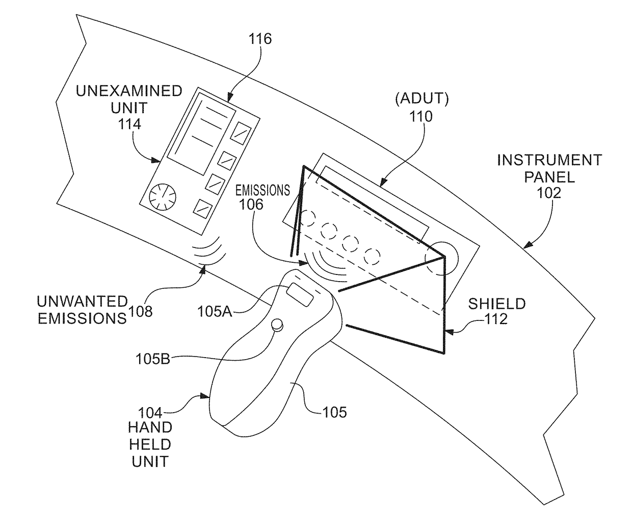
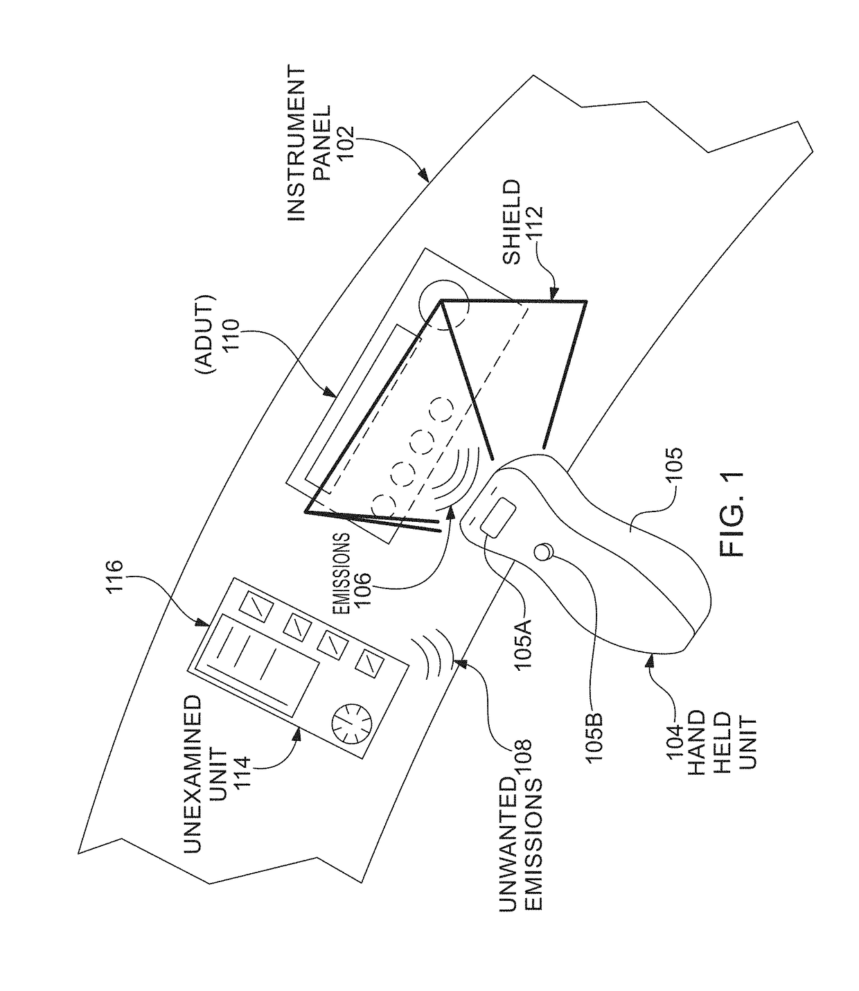
A hand-held apparatus for analysis, testing, inspecting and / or screening a fully integrated and assembled electrically powered assets and devices for measurement of degree of device aging, degradation, condition, and / or Remaining Useful Life (RUL). The device includes an on-board antenna positioned at a distance from the electrically powered device under test and a signal receiver or sensor for examining a signal from the electrically powered device, but especially applied to electronic devices. The receiver or sensor collects unintended and / or intended RF energy components emitted by the electrically powered device and performs the above analysis in a response to the acquired signal input while the electrically powered device is active or powered.

Description

CROSS REFERENCE TO RELATED APPLICATIONS[0001]The present non-provisional application is related to and claims benefit of and priority from provisional U.S. patent application Ser. No. 62 / 490,244, titled “Electronics equipment testing apparatus and method utilizing unintended RF emission features” and filed on Apr. 26, 2017 by Applicant Nokomis Inc., the entire contents of which are hereby incorporated by reference thereto. This present non-provisional application is also related to a co-pending non-provisional application Ser. No. ______, titled “Electronics card insitu testing apparatus and method utilizing unintended RF emission features”, which is incorporated hereby in its entirety by reference thereto.[0002]This document incorporates by reference the entire contents of disclosures and / or teachings of the following documents: U.S. Pat. No. 7,515,094 entitled “Advanced electromagnetic location of electronic equipment”; U.S. Pat. No. 8,063,813 entitled “Active improvised explosive...

Claims


Application Information

Patent Timeline
Patent Type & Authority Applications(United States)
IPC IPC(8): G01R23/02H01Q13/02H04B1/16G01R29/08G01R31/00
CPCG01R23/02H01Q13/02H04B1/16G01R29/0878G01R31/003H01Q1/36
Inventor BRANT, ADAMKELLER, III, WALTER J.CHORNENKY, TODD ERIC
Owner NOKOMIS
Learn More