
Device for controlling supply of working fluid

a technology for working fluid supply and working fluid, applied in water feed control, steam engine plants, steam regeneration, etc., can solve the problems of increasing cost and reducing economic efficiency, and achieve the effect of efficient and economic control

Active Publication Date: 2018-10-04
DOOSAN HEAVY IND & CONSTR CO LTD
View PDF0 Cites 6 Cited by
  • Summary
  • Abstract
  • Description
  • Claims
  • Application Information

AI Technical Summary

Benefits of technology

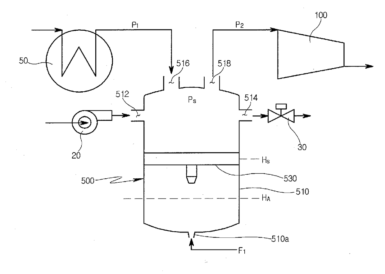
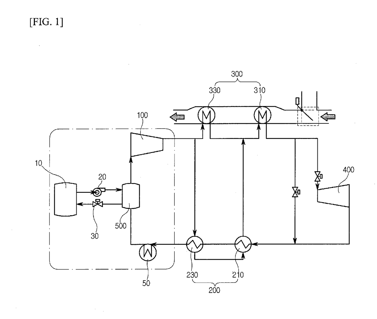
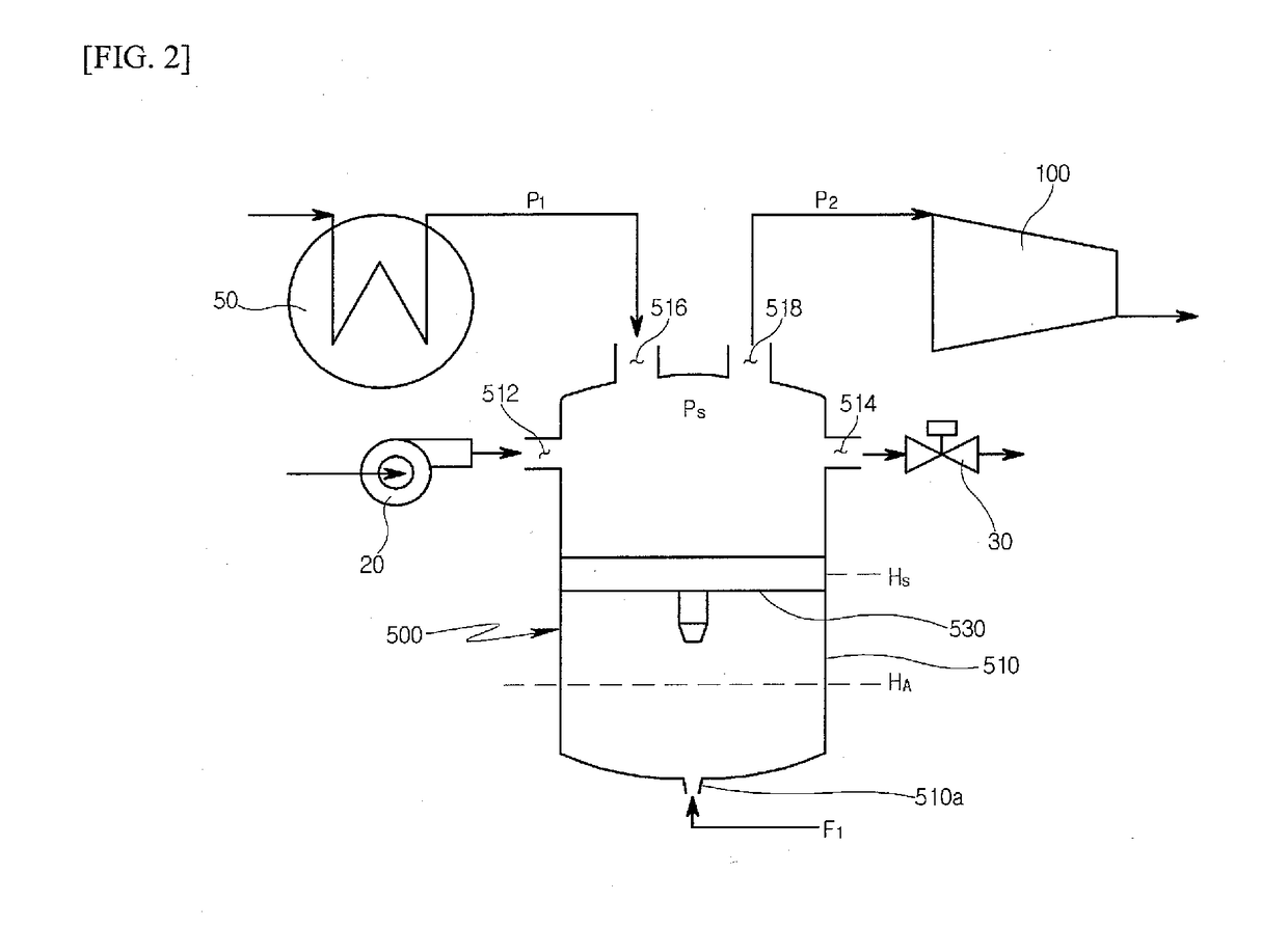
The purpose of this invention is to create a device that can control the supply of a fluid used in power generation. The device can efficiently and economically control the fluid's flow rate and pressure to supply it into the power generation cycle.

Problems solved by technology

Therefore, since the mass control tank is connected to the high pressure line of the outlet of the compressor, it is essential that the mass control tank is made of expensive materials and components capable of withstanding the high pressure, which leads to an increase in cost and a decrease in economical efficiency.

Method used


Image

  • Device for controlling supply of working fluid
  • Device for controlling supply of working fluid
  • Device for controlling supply of working fluid

Examples


Embodiment Construction

[0035]Hereinafter, a device for controlling a supply of a working fluid according to an exemplary embodiment of the present disclosure will be described in detail with reference to the accompanying drawings.

[0036]Generally, the power generation system using supercritical CO2 configures a close cycle in which CO2 used for power generation is not emitted to outside, but uses supercritical CO2 as a working fluid.

[0037]The power generation system using supercritical CO2 can use exhaust gas emitted from a thermal power plant or the like since a working fluid is the supercritical CO2. Accordingly, the power generation system using supercritical CO2 may not only be used as a single power generation system, but also be used for a hybrid power generation system with the thermal power generation system. The working fluid of the power generation system using supercritical CO2 may also supply CO2 separated from the exhaust gas and may also supply CO2 separately.

[0038]Supercritical CO2 (hereinaf...


PUM


Abstract

A device for controlling a supply of a working fluid to a power generation cycle with a compressor compressing the working fluid and a precooler cooling the working fluid supplied to the compressor comprises a storage tank storing the working fluid supplied to the power generation cycle and a flotation tank disposed between the precooler and the compressor to flow or temporarily store the working fluid, wherein a pressure within the flotation tank and a flow rate of the working fluid are controlled based on pressures at an inlet of the compressor and an outlet of the precooler.

Description

CROSS-REFERENCE(S) TO RELATED APPLICATIONS[0001]This application claims priority to Korean Patent Application No. 10-2017-0039383, filed on Mar. 28, 2017 the disclosure of which is incorporated herein by reference in its entirety.BACKGROUND OF THE DISCLOSUREField of the Disclosure[0002]Exemplary embodiments of the present disclosure relate to a device for controlling a supply of a working fluid, and more particularly, to a device for controlling a supply of a working fluid capable of efficiently and economically controlling a flow rate and a pressure of the working fluid to supply the working fluid into a power generation cycle.Description of the Related Art[0003]Various efforts for increasing a power output while decreasing the emission of pollutants have been made. As one of such efforts, research and development of a power generation system using supercritical CO2 as a working fluid have been actively conducted.[0004]Because supercritical CO2 has a density similar to the liquid s...

Claims


Application Information

Patent Timeline
Patent Type & Authority Applications(United States)
IPC IPC(8): F01K25/10F01K3/16F01K13/00F01K7/16
CPCF01K25/103F01K3/16F01K13/006F01K7/165F22D3/00F22D5/06F01K7/32F01K19/04
Inventor PARK, SANG SINKANG, SEUNG GYUHWANG, JEONG HOLEE, HYO SEONG
Owner DOOSAN HEAVY IND & CONSTR CO LTD
Learn More