
Control system

a control system and control system technology, applied in the direction of flow control, liquid/fluent solid measurement, relative volume flow measurement, etc., can solve the problems of agitation of components, forced mixing of components, and difficult control of such systems

Active Publication Date: 2018-08-30
OLITEK PTY LTD
View PDF0 Cites 3 Cited by
  • Summary
  • Abstract
  • Description
  • Claims
  • Application Information

AI Technical Summary

Benefits of technology

The present invention is about a control system and method for a fluid delivery system. The invention uses pump maps to control the operation of pumps, which improves accuracy in short pumping sequences. The system also allows for continued operation if there is a failure in a feedback device. Additionally, the system includes a back pressure valve that helps mix components and control back pressure downstream of the pump. The controller can also determine the required speed for retracting the hose. Overall, this invention provides a more accurate and efficient way to control the fluid delivery system.

Problems solved by technology

However, some fluid delivery systems undergo repeated start-up processes.
Control of such systems has been found to be problematic.
This flow restriction causes the components to shear within the piping, agitating the components and forcing them to mix.
The short time requirement often leaves no time for traditional control methods to be effective.
Unfortunately, when short shot times are required, conventional control methodologies are not able to achieve the requisite level of control over the flowrate, composition and backpressure in the fluid delivery system.

Method used


Image

  • Control system
  • Control system
  • Control system

Examples


Embodiment Construction

[0055]Those skilled in the art will appreciate that the attached drawings have been provided for the purposes of describing preferred embodiments of the present invention. Therefore, it will be understood that the present invention should not be considered to be limited solely to the features as shown in the attached drawings.

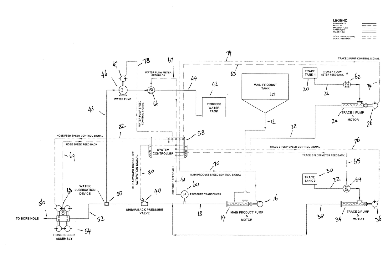
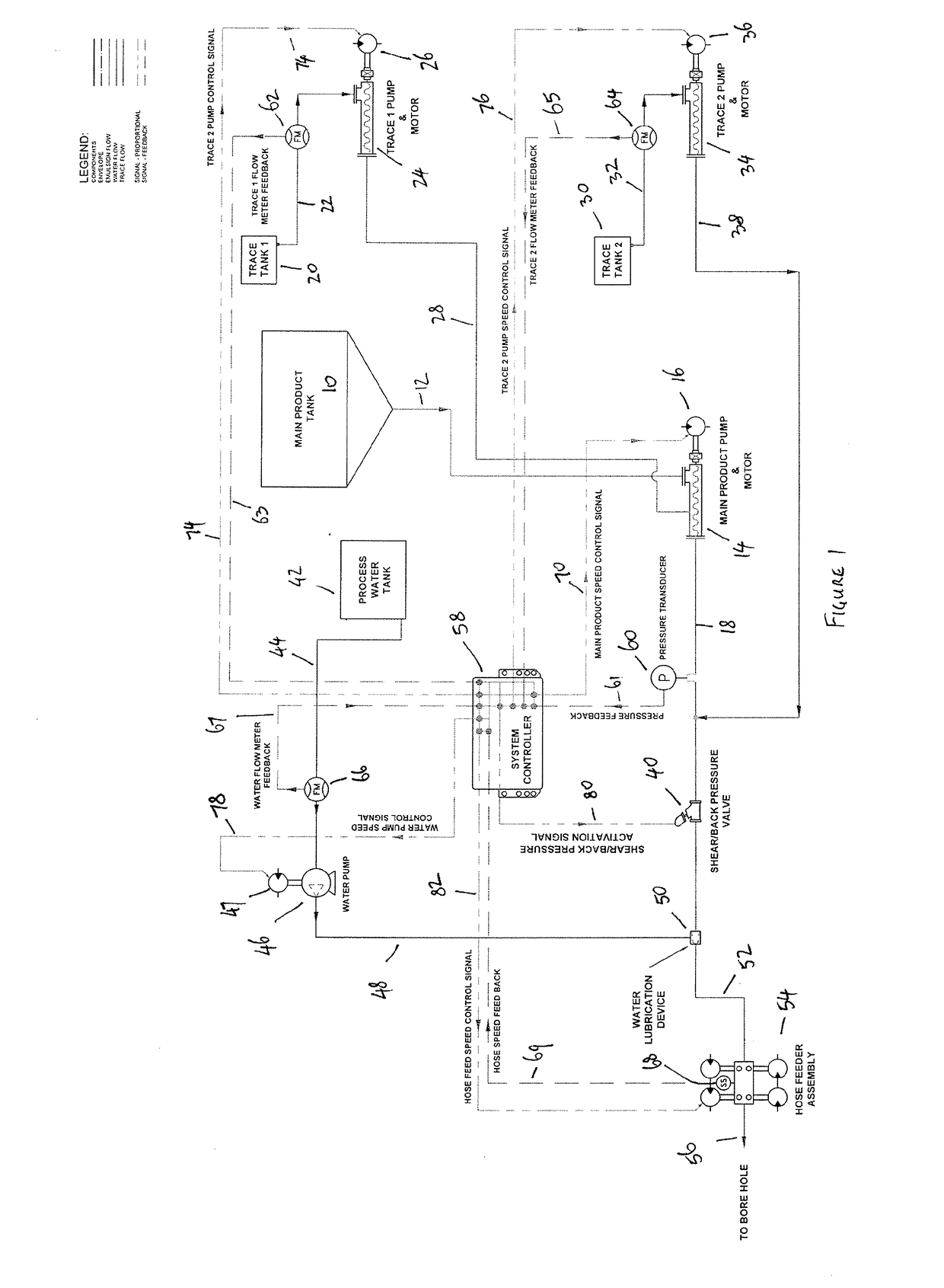
[0056]FIG. 1 shows a process control flowsheet for an apparatus for delivering a fluid. In the specific embodiment shown in FIG. 1, the apparatus is designed for delivering an emulsion explosive to a shot hole drilled into a mine or an ore body. The apparatus shown in FIG. 1 is particularly useful for preparing and delivering on-site explosives. When delivering such emulsion explosives to a shot hole, it is often necessary to mix the main explosive emulsion with one or more trace chemicals, with the trace chemicals being present in a specified percentage of the main emulsion. Close control of the amount of trace chemicals that are added is important.

[0057]The a...


PUM


Abstract

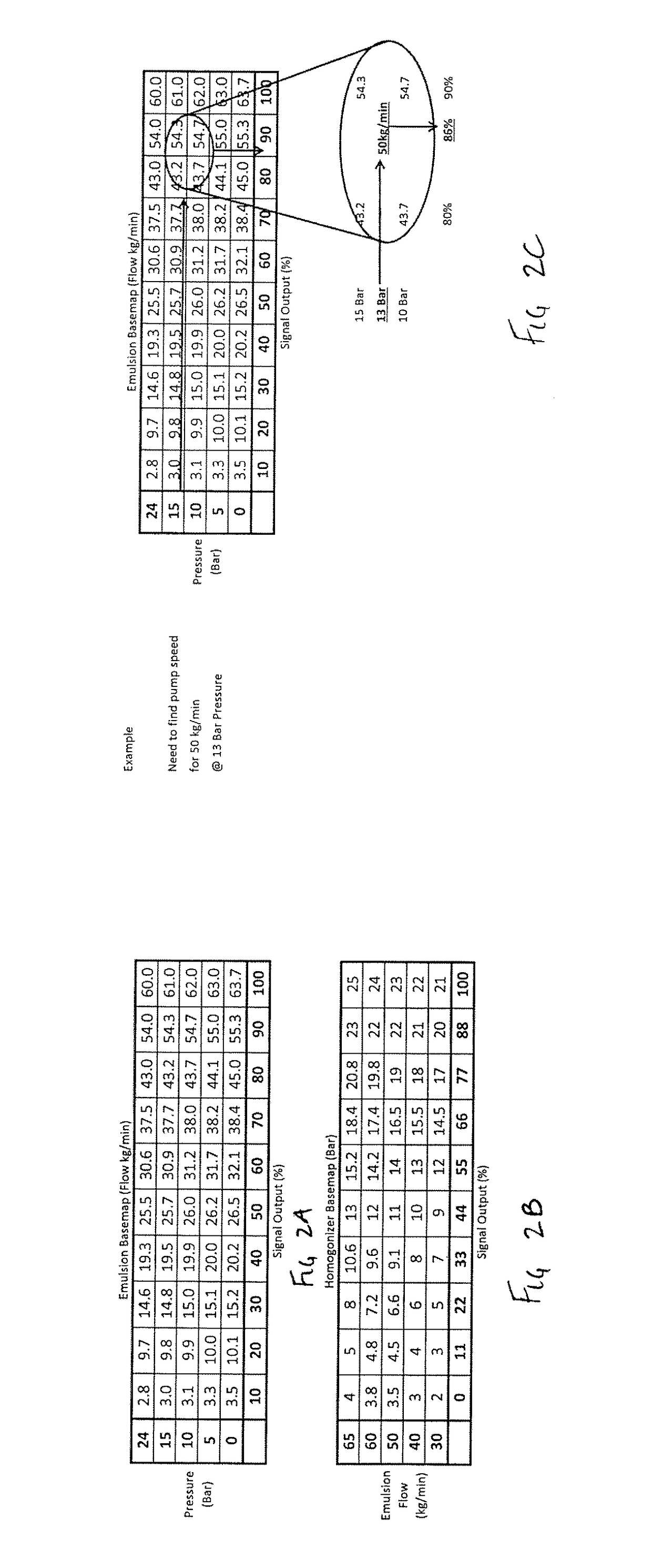
A control system for controlling operation of a fluid delivery system that includes at least a first pump (14) for delivering a first fluid and a second pump (24) for mixing a second fluid with the first fluid. The control system includes a controller (58), the controller including a first pump map for the first pump (14), the first pump map having a first pump flow rate mapped against one or more variables including a control output signal, the controller (58) including a second pump map for the second pump (24), the second pump map having a second pump flow rate mapped against one or more variables including a control output signal, the controller (58) determining the control output signal for the first pump (14) to obtain a desired flow rate from the first pump, the controller determining the control output signal for the second pump (24) to obtain a target flow rate and a target percentage of the second fluid relative to the first fluid or a target percentage of the second fluid relative to an overall fluid flow, the respective control output signals for the first pump (14) and the second pump(24) being determined using the first pump map and the second pump map, respectively.

Description

TECHNICAL FIELD[0001]The present invention relates to a control system and method for controlling a fluid delivery system.BACKGROUND ART[0002]Control systems are widely used to control fluid flow rates and pressures through pipes and hoses in fluid delivery systems. For example, many large scale chemical plants have piping systems that supply different fluids to reaction vessels. The fluids must be supplied to the reaction vessels at desired flowrates and in desired proportions to ensure that the required reactions take place in the reaction vessels to obtain a desired product flow rate from the reaction vessel that includes minimal unreacted reactants or unwanted by-products.[0003]Conventional control systems used in chemical plants typically include pressure transducers and flowrate measurement devices that provide information back to controllers. The controllers will typically compare the measured parameters of pressure and flowrate against desired target pressures on flowrates. ...

Claims


Application Information

Patent Timeline
IPC IPC(8): F42D1/10G01F9/00G05D7/06G05D11/13
CPCF42D1/10G01F9/00G05D7/0682G05D11/132G05D7/00
Inventor OLIVER, JAMESPAECH, SIMON BENJAMIN
Owner OLITEK PTY LTD
Learn More