
Systems and Methods for Creating Custom-Fit Exoskeletons

a technology of exoskeleton and control interface, which is applied in the field of system and method for creating custom-fit exoskeletons, can solve the problems of complicated exoskeleton control interface, difficult to construct exoskeleton control interface, and complicating the proper fitting of an exoskeleton

Inactive Publication Date: 2018-08-30
EKSO BIONICS
View PDF0 Cites 7 Cited by
  • Summary
  • Abstract
  • Description
  • Claims
  • Application Information

AI Technical Summary

Benefits of technology

The present invention describes a device and method for quickly measuring and modeling the surface and subsurface of a person. This allows for the creation of personalized exoskeleton parts that can be designed and manufactured to fit the measured person. The device can also measure a person in multiple poses and create a unified surface and subsurface model of the person. This unified model can help to design better exoskeleton parts that move more like a person's natural movements. The invention can also generate modified exoskeleton trajectories based on the unified model and upload them to the exoskeleton control system of the personalized powered exoskeleton. Overall, this device and method can provide a faster and more precise way to measure and design personalized exoskeleton parts for people with mobility issues.

Problems solved by technology

It is highly complex and difficult to construct an exoskeleton control interface that enables the full range of modification desired by a physical therapist during rehabilitation.
However, the proportions of people are highly variable, thereby complicating the proper fitting of an exoskeleton.
Still, even with a well-designed adjustable exoskeleton and a skilled technician, the fit to a specific user may not be optimal in some cases.
However, the adoption of custom-manufactured exoskeleton parts using current methods is limited by the cost of personalized manufacture, the skillsets required for custom exoskeleton design and the time lag between measurement or fitting of a user and delivery of the custom parts.

Method used


Image

  • Systems and Methods for Creating Custom-Fit Exoskeletons
  • Systems and Methods for Creating Custom-Fit Exoskeletons
  • Systems and Methods for Creating Custom-Fit Exoskeletons

Examples


first embodiment

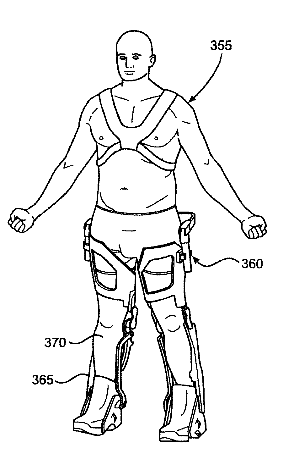
[0048]Turning to FIG. 3A, there is shown a flow chart illustrating a method in accordance with the present invention. At step 300, one or more 3D scans of a person are performed in which the surface contours of the person are measured. At step 305, the 3D scan data from step 300 is used to generate a 3D surface computer model of the person. At step 310, the 3D surface model of the person is used to generate a 3D exoskeleton components model that will optimally fit the 3D surface model of the person. At step 315, 3D printing is used to fabricate exoskeleton components based on the 3D exoskeleton model generated in step 310. At step 320, a technician or physical therapist assembles the 3D printed exoskeleton components into an exoskeleton. At step 325, a technician or physical therapist fits the assembled exoskeleton to the person measured in step 300, confirms proper fit and makes further adjustments as needed.

[0049]With reference to FIG. 3B, a 3D surface scan of a person in accordan...

second embodiment

[0054]Turning to FIG. 4A, there is shown a flow chart illustrating a method in accordance with the present invention. At step 400, one or more 3D scans of a person are performed for each of a plurality of poses. As a result, the surface contours of the person are measured in each of the poses. Since muscles and other tissues swell with contraction, the 3D surface of the person changes as the body of a person assumes the various poses. At step 405, the 3D scan data from step 400 is used to generate a 3D surface computer model of the person for each pose. At step 410, the 3D surface models of the person are compiled into a single, unified 3D surface model that takes into account the changing surface contours of the person in the various poses. At step 415, the unified 3D surface model is used to generate a 3D exoskeleton components model that will optimally fit the unified 3D surface model of the person. At step 420, 3D printing is used to fabricate exoskeleton components based on the...

third embodiment

[0059]Turning to FIG. 5A, there is shown a flow chart illustrating a method in accordance with the present invention. At step 500, one or more 3D surface scans of a person are performed with the person in one or more poses. At step 505, the 3D scan data from step 500 is used to generate one or more 3D surface computer models of the person. At step 510, one or more subsurface scans of the person are performed with the person in one or more poses. At step 515, the subsurface scan data from step 510 is used to create one or more subsurface models of the person. At step 520, the one or more 3D surface models and the one or more subsurface models are compiled into a single, unified model of the person that takes into account both surface and subsurface features of the person in the one or more poses. At step 525, the unified 3D model generated in step 520 is used to generate a 3D exoskeleton components model that will optimally fit the unified 3D model of the person. At step 530, 3D prin...


PUM

PropertyMeasurementUnit
Trajectoryaaaaaaaaaa

Abstract

A three-dimensional surface scan of an exoskeleton wearer is performed to generate three-dimensional surface data, and a three-dimensional surface model of the exoskeleton wearer is generated from the three-dimensional surface scan data. A three-dimensional exoskeleton model is generated from the three-dimensional surface model. At least one three-dimensional exoskeleton component is printed from the three-dimensional exoskeleton model, and a custom-fit exoskeleton is assembled using the at least one three-dimensional exoskeleton component.

Description

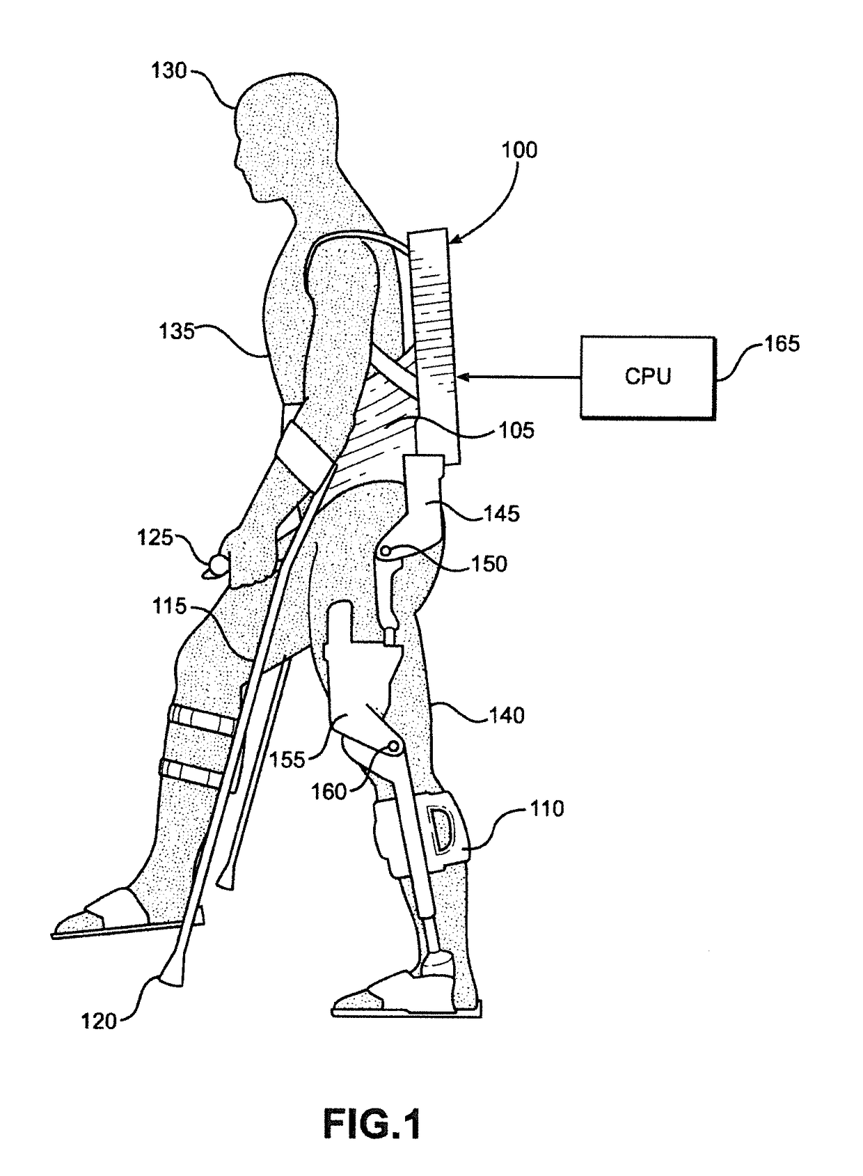
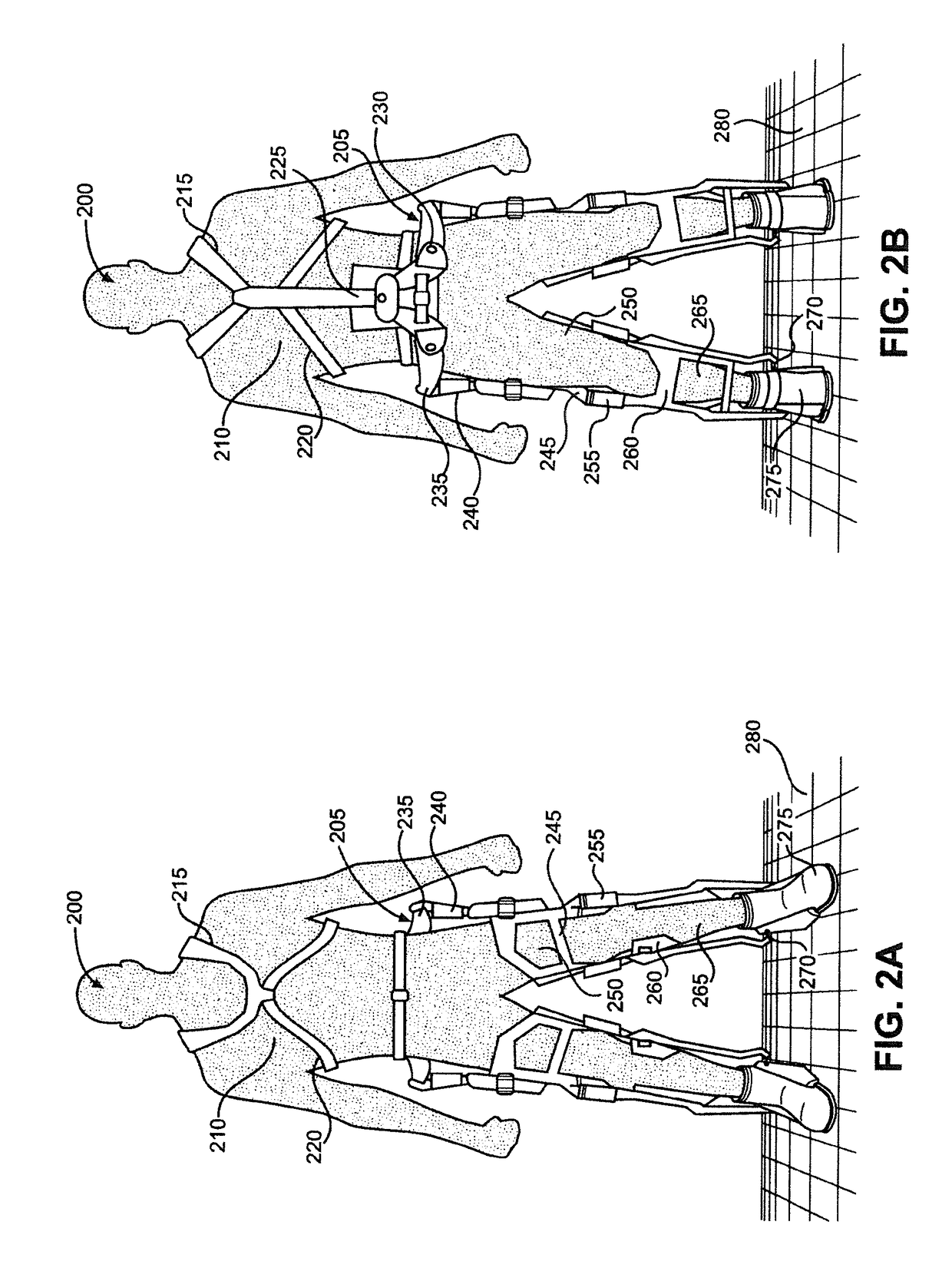
FIELD OF THE INVENTION[0001]The present invention relates to devices and methods that augment a user's strength or aid in the prevention of injury during the performance of certain motions or tasks. More particularly, the present invention relates to devices and methods suitable for use by a person engaging in heavy tool use or weight bearing tasks or to devices and methods suitable for therapeutic use with patients that have impaired neuromuscular or muscular function of the appendages. These devices comprise a set of artificial limbs, and in some cases related control systems and actuators, that potentiate improved function of the user's appendages for activities including, but not limited to, enabling walking for a disabled person, granting greater strength and endurance in a user's arms or allowing for more weight to be carried by the user while walking.BACKGROUND OF THE INVENTION[0002]Wearable exoskeletons have been designed for medical, commercial and military applications. Me...

Claims


Application Information

Patent Timeline
IPC IPC(8): A61H3/00G01B11/24G06T17/00G06T19/20B33Y50/00B33Y80/00
CPCA61H3/00G01B11/24G06T17/00G06T19/20B33Y50/00B33Y80/00A61B5/1079A61H2201/1207A61H2201/164A61H2201/1628A61H2201/1647A61H2201/165A61H2201/5007A61H3/02A61H2003/007F41H1/02F41H5/013G06T2200/08G06T2219/2008A61F5/01B33Y30/00A61B5/0064B33Y10/00Y10T29/49826
Inventor ANGOLD, RUSSPREUSS, ADAMFLEMING, NICHOLASAMUNDSON, KURT
Owner EKSO BIONICS
Learn More