Image forming apparatus performing calibration, and control method therefor

a technology of image forming apparatus and calibration method, which is applied in the direction of electrographic process apparatus, visual presentation, instruments, etc., can solve the problems of large output value of light receiving element, large error of value that is converted from density, and large high-density area under low irradiation light amount, so as to improve the quality of printed image and improve the measurement accuracy of pattern image.

Active Publication Date: 2018-08-16
CANON KK
View PDF0 Cites 1 Cited by
  • Summary
  • Abstract
  • Description
  • Claims
  • Application Information

AI Technical Summary

Benefits of technology

[0009]The present invention provides a technique that sets up an irradiation light amount appropriately to improve measurement accuracy of a pattern image and improves quality of a printed image.

Problems solved by technology

On the other hand, when an irradiation light amount is too low and a reflected light amount decreases too much, output variation of the light receiving element in response to density variation of a pattern image becomes small, which enlarges an error of a value that is converted from the density.
Since variation of the output of the light receiving element in response to variation of gradation of the pattern image becomes small in a high-density area of the pattern image, an error of a value that is obtained by converting the density of a detection result in the high-density area becomes large under a low irradiation light amount.
On the other hand, when the irradiation light amount is always high, the reflected light amount from a low-density area of the pattern image or from the image bearing member becomes so large that the output value of the light receiving element is saturated, which disturbs correct detection of the density.
Namely, it was difficult to accurately detect density of a pattern image in a wide density range.
An error becomes large when the high-density pattern image is measured with a low irradiation light amount.

Method used


Image

  • Image forming apparatus performing calibration, and control method therefor
  • Image forming apparatus performing calibration, and control method therefor
  • Image forming apparatus performing calibration, and control method therefor

Examples


first embodiment

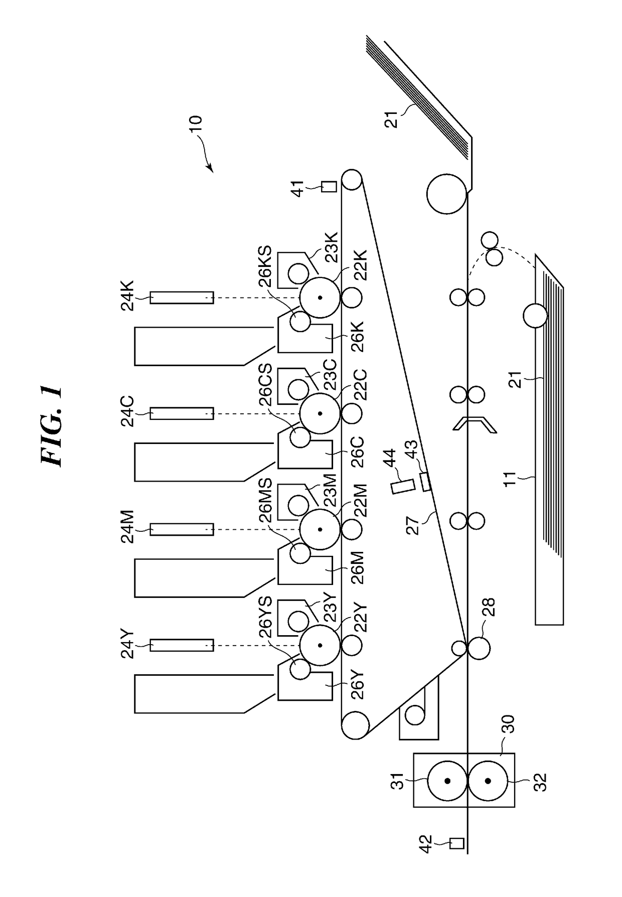
[0031]FIG. 1 is a view showing a configuration of a printer of an image forming apparatus according to the present invention. The image forming apparatus is a color image forming apparatus (printer) of an electrophotographic system. The printer 10 has four stations for forming images of four colors including yellow (Y), magenta (M), cyan (C), and black (K).

[0032]The printer 10 is provided with laser light sources 24Y, 24M, 24C, and 24K, photosensitive drums 22Y, 22M, 22C, and 22K, electrostatic chargers 23Y, 23M, 23C, and 23K, and development devices 26Y, 26M, 26C, and 26K corresponding to the four colors. Moreover, the development devices 26Y, 26M, 26C, and 26K are respectively provided with sleeves 26YS, 26MS, 26CS, and 26KS.

[0033]The photosensitive drums 22Y, 22M, 22C, and 22K are constituted by applying an organic photoconductive layer to a periphery of an aluminum cylinder, and are rotated by driving force of a drive motor (not shown). This drive motor rotates the photosensitiv...

second embodiment

[0095]FIG. 13 is a view showing an example of a pattern image P2 for development-contrast correction used in the Dmax control. The pattern image P2 is formed on the intermediate transfer belt 27 in the It should be noted that the pattern image P2 is enough to be formed on an image bearing member, and may be formed on the photosensitive drum 22Y, 22M, 22C, or 22K. For example, when the pattern sensor 41 measures a pattern image formed on the photosensitive drum 22Y, for example, the pattern sensor 41 is enough to be arranged opposite to the photosensitive drum 22Y on which measurement images are formed.

[0096]An arrow in FIG. 13 indicates the rotational direction of the intermediate transfer belt 27. The pattern image P2 is a group of measurement images each of which is a square with a one-side of 25 mm. Five measurement images are formed for each of Y, M, C, and K in the pattern image P2 while changing the development contrast in five steps of V1, V2, V3, V4, and V5 by changing char...


PUM


Abstract

An image forming apparatus that enhances measurement accuracy of a pattern image and improves quality of a printed image. Light emitted from a light emission unit based on a first measurement condition is reflected from an image bearing member, and first information is generated based on a measurement result of the image bearing member. Second information is determined based on the first measurement condition, the first information, and a second measurement condition. Light is emitted based on the first measurement condition when a first measurement image is measured, and an image forming condition is generated based on a measurement result of the first measurement image and the first information. Light is emitted based on the second measurement condition when a second measurement image is measured, and the image forming condition is generated based on a measurement result of the second measurement image and the second information.

Description

BACKGROUND OF THE INVENTIONField of the Invention[0001]The present invention relates to a calibration technique of an image forming apparatus.Description of the Related Art[0002]Generally, an image forming apparatus performs calibration to correct deviation between target density and density of an actually printed image owing to a change of an environment around the apparatus or secular changes of parts of the apparatus. It is important to reduce deviation of density also in a color image forming apparatus because a color balance (what is called a color tone) varies when image density of each color shifts. In calibration, a pattern image formed on an image bearing member is measured. Then, image forming conditions are adjusted so that density of an output image becomes target density. It should be noted that the image forming conditions include an exposure, developing bias, and a γ correction table. The exposure and the developing bias are controlled in order to correct the maximum ...

Claims


Application Information

Patent Timeline
Patent Type & Authority Applications(United States)
IPC IPC(8): G03G15/00G03G15/043H04N1/00
CPCG03G15/043H04N1/00761G06K15/027H04N1/4052G03G15/5058G03G2215/00042H04N1/6036
Inventor TOMII, HIROSHI
Owner CANON KK
Why Eureka
Try Eureka