
Submersible electric thruster

a technology of electric thruster and submerged body, which is applied in the field of thrusters, can solve the problems of laborious maintenance, large design of common thruster compared to electric motor, and large size of common thruster cylinders, and achieve the effect of facilitating illustration and description

Inactive Publication Date: 2018-08-16
BLUE ROBOTICS
View PDF8 Cites 12 Cited by
  • Summary
  • Abstract
  • Description
  • Claims
  • Application Information

AI Technical Summary

Benefits of technology

This patent describes a small, compact, and affordable thruster that can be used in submersible vehicles. The design with its stator and rotor assemblies is unique and addresses several needs including operating at the full depth of the ocean, requiring minimal maintenance, and being affordable for hobbyist, academic, and commercial use. The thruster is designed to be connected to a nozzle and tail cone for water flow and includes a protective coating. The technical effects of this invention include improved efficiency, reliability, and durability of submersible vehicles.

Problems solved by technology

Common thruster designs are generally very large compared to an electric motor of equivalent power that is not sealed from the water.
Electric thrusters are generally limited to depths of around 300-3,000 feet because they have air- or oil-filled cavities that are affected by the very high pressures experienced at depth.
Most ROVs have between three to six thrusters, making maintenance a laborious task.
Additionally, for long endurance applications, such as long-endurance ASVs and AUVs, routine maintenance is not an option as the vehicles could be operated for months at a time.
Last, currently available thrusters are prohibitively expensive and consequently restricted from use in many applications such as hobby use, academic use, and small business commercial use.
Much of the cost is driven by the complexity and number of parts used in typical designs.

Method used


Image

  • Submersible electric thruster
  • Submersible electric thruster
  • Submersible electric thruster

Examples


Embodiment Construction

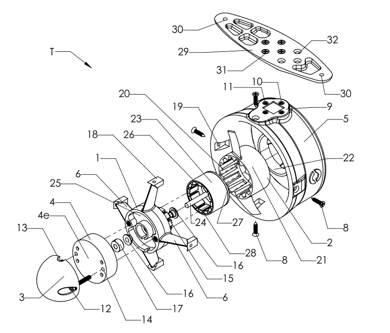
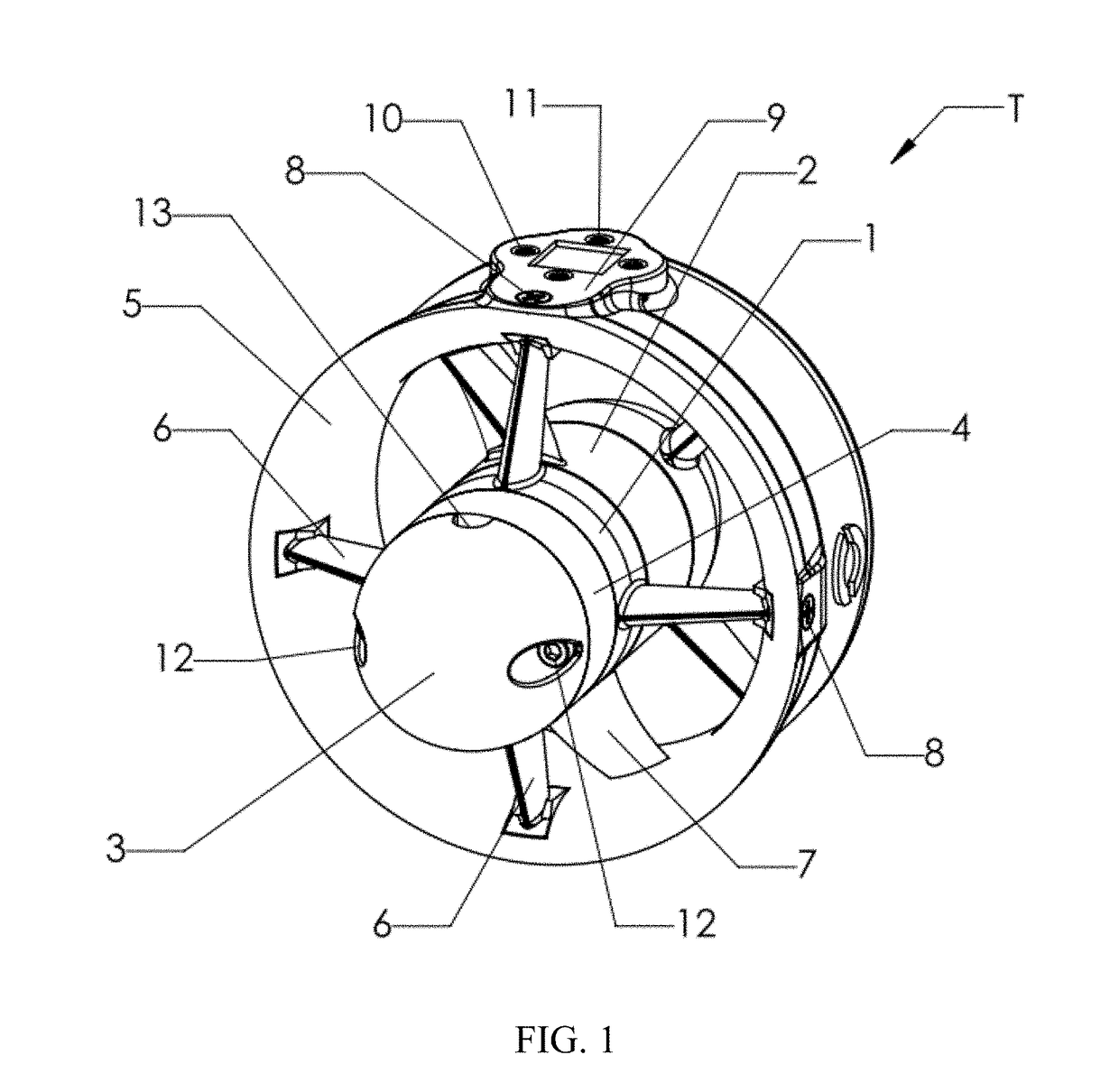
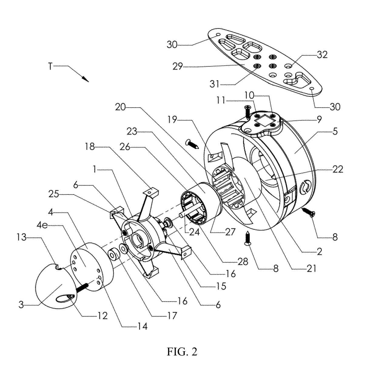
[0038]The present embodiments generally relate to a submersible electric thruster that has a number of unique benefits including a compact size, operability at the full depth of the ocean, zero or minimal required maintenance, low number of parts, and low cost relative to currently available alternatives. Unlike most thrusters, which generally consist of a motor disposed in an air or oil filled cavity and connected to a propeller through a mechanical or magnetic connection, the present invention uses a novel design that seals the individual components of the motor without creating any cavities or requiring seals or magnetic couplings. In addition to reducing the size and number of parts, this allows the thruster to operate at extreme pressures at the bottom of the ocean without issue and to operate continuously for extended periods of time without maintenance. These unique features combined with the low number of parts and overall simplicity of the design produce a thruster that is ...


PUM


Abstract

A submersible electric thruster operable to propel underwater vehicles, surface vehicles, amphibious vehicles, etc. The submersible electric thruster includes a stator assembly having a base, stator, windings, and bearings and an external rotor assembly having a cylindrical arrangement of permanent magnets with a hub that is secured to a shaft. The stator forms the center of the motor and the permanent magnets spin around the stator. A propeller hub is integrally connected to the rotor assembly with angularly spaced propeller blades extending radially from the propeller hub. An annular nozzle surrounds the propeller and motor, forming an inlet and outlet for water flow. A nose cone is connected to the stator assembly and a tail cone is integrally connected to the nozzle assembly. Supporting arms may extend from the stator assembly to support the nozzle and / or supporting arms may extend from the nozzle to the support the tail cone.

Description

RELATED APPLICATIONS[0001]This application is a continuation-in-part of U.S. application Ser. No. 14 / 699,478 filed on Apr. 29, 2015, which claims the benefit of U.S. Provisional Application No. 61 / 986,945 filed on May 1, 2014, all of which are hereby incorporated herein by reference in their entireties.FIELD OF THE INVENTION[0002]The present invention relates to a thruster and in particular to a submersible electric thruster.[0003]The invention is a unique design that has a low number of parts, no enclosed air or oil cavities, and requires minimal maintenance.BACKGROUND OF THE INVENTION[0004]Unmanned and robotic marine vehicles, such as remotely operated underwater vehicles (ROVs), autonomous underwater vehicles (AUVs), and autonomous surface vessels (ASVs), have become invaluable tools for marine exploration. They are commonly used for scientific, industrial, commercial, and recreational purposes. These vehicles generally use thrusters for propulsion.[0005]A thruster is a device wh...

Claims


Application Information

Patent Timeline
IPC IPC(8): B63H23/24B63H1/20B63H5/15B63H21/17B63H21/21H02K5/132H02K7/14H02K3/44
CPCB63H23/24B63H1/20B63H5/15B63H21/17B63H21/21H02K5/132H02K7/14H02K3/44B63H2021/216H02K21/22H02K11/33B63B2035/006B63B2209/18B63B2211/02B63H2011/081
Inventor JEHANGIR, RUSTOM F.SPADOLA, JOSEPH A.SIMKO, ADAM
Owner BLUE ROBOTICS
Learn More