Image reading device
a reading device and image technology, applied in the direction of electrographic process apparatus, instruments, printers, etc., can solve the problem of changing the movement speed and achieve the effect of simple configuration and reliable suppression of the speed variation of the image reading uni
- Summary
- Abstract
- Description
- Claims
- Application Information
AI Technical Summary
Benefits of technology
Problems solved by technology
Method used
Image

Examples
embodiment 1
[0025]Hereinafter, embodiments of the present invention will be described in detail on the basis of the drawings. It is noted that the present invention is not limited to the following embodiments.
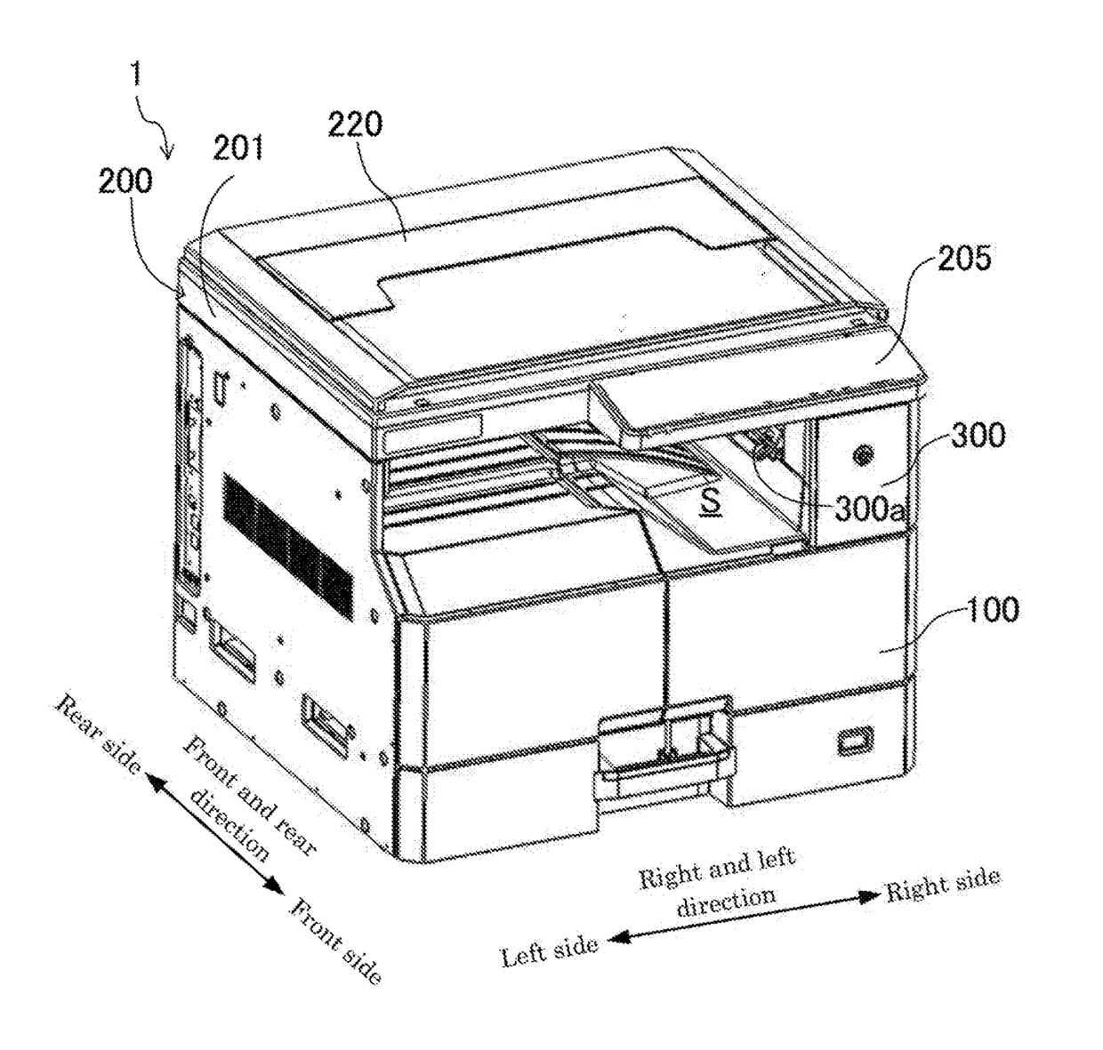
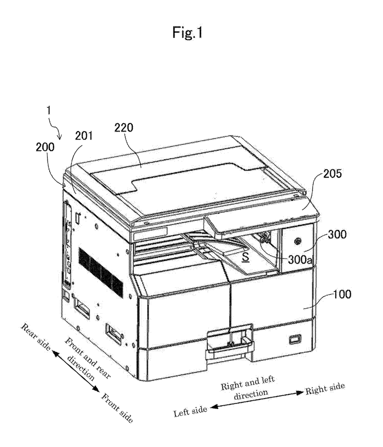
[0026]FIG. 1 illustrates an image forming apparatus 1 including an image reading device 200 of the present embodiment. The image forming apparatus 1 is so-called an in-body sheet discharge type copy machine and has an image forming apparatus body 100, the image reading device 200, and a support casing 300. The image reading device 200 reads a document image to acquire image data thereof. In the image forming apparatus body 100, the image data acquired by the image reading device 200 is printed on a sheet P. The image reading device 200 is supported to an upper side of the image forming apparatus body 100 via the support casing 300. Between the image forming apparatus body 100 and the image reading device 200, a sheet discharge space S is formed. The image reading device 200 is provided at ...
modification example
[0042]FIG. 7 illustrates a modification example 1 of the aforementioned embodiment 1. In this modification example 1, a plate-like protruding wall part 212b is formed at the other side surface of the carriage 212 in the sub-scanning direction, so that the inclination surface 212a is formed. That is, the protruding wall part 212b is upwardly inclined from the one side toward the other side in the main scanning direction, so that the inclination surface 212a serves as a lower side surface of the protruding wall part 212b.
[0043]According to the modification example 1, it is possible to obtain operation and effect similar to those of the aforementioned embodiment 1.
embodiment 2
[0044]FIG. 8 illustrates an embodiment 2. This embodiment 2 is different from the aforementioned embodiment 1 and the modification example in that the angle restriction part for restricting the angle of the flat cable 214 is configured by the connecting connector 216 itself.
[0045]That is, in the present embodiment 2, the connecting connector 216 is upwardly inclined toward one side from the other side in the main scanning direction. According to this configuration, the upper sidewall part 214a of the flat cable 214 connected to the connecting connector 216 is upwardly inclined from the one side toward the other side in the main scanning direction. Consequently, when the curvature radius R of the curved part 214c of the flat cable 214 increases during the movement of the carriage 212 and the upper sidewall part 214a of the flat cable 214 contacts with the document table glass 203, contact portions of the both can be biased to one side of the flat cable 214 in the main scanning direct...
PUM
 Abstract
Description
Claims
Application Information
 - R&D
- Intellectual Property
- Life Sciences
- Materials
- Tech Scout
- Unparalleled Data Quality
- Higher Quality Content
- 60% Fewer Hallucinations
Browse by: Latest US Patents, China's latest patents, Technical Efficacy Thesaurus, Application Domain, Technology Topic, Popular Technical Reports.
© 2025 PatSnap. All rights reserved.Legal|Privacy policy|Modern Slavery Act Transparency Statement|Sitemap|About US| Contact US: help@patsnap.com