
Cooling fans for engine cooling system

a technology for cooling fans and engines, applied in the field of cooling fans, can solve the problems of cooling fans that may be noisy, noise objectionable to vehicle customers, cooling fans, etc., and achieve the effects of reducing fuel economy, reducing fuel economy, and reducing airflow to the engine compartmen

Active Publication Date: 2018-08-09
FORD GLOBAL TECH LLC
View PDF8 Cites 6 Cited by
  • Summary
  • Abstract
  • Description
  • Claims
  • Application Information

AI Technical Summary

Benefits of technology

The invention is a new engine cooling system that solves problems with traditional cooling fans. The system includes a bladeless cooling fan with reduced noise and higher performance characteristics. The fan includes a plurality of discs and a shroud that is positioned between the radiator and the engine. The fan also has a hollow central opening that allows unrestricted ambient airflow. A Helmholtz resonator can be included within the fan to increase its efficiency. The use of a bladeless source fan and the corresponding Helmholtz resonator reduces noise output and improves fan performance. The system also makes it easier for service technicians to reach into the engine compartment while the fan is running.

Problems solved by technology

As one example, cooling fans may be very noisy, especially when operated at high flow settings.
The noise may be objectionable to vehicle customers.
As another example, cooling fans may reduce fuel economy.
Although cooling fans are not on for a significant portion of a drive cycle, the blades and shrouds of the fan may continue to create a slight restriction, which reduces fuel economy and reduces airflow to the engine compartment.
As yet another example, the location of the cooling fans relative to the radiator may make it difficult for a person (e.g., a service technician) to reach toward the radiator when the engine is running (e.g., during a service or cleaning procedure).
Furthermore, the cooling fans may be inefficient.
By using a bladeless source fan, the noise output by the fan is reduced, as well as efficiency losses associated with flow restriction caused by fan blades.

Method used


Image

  • Cooling fans for engine cooling system
  • Cooling fans for engine cooling system
  • Cooling fans for engine cooling system

Examples


Embodiment Construction

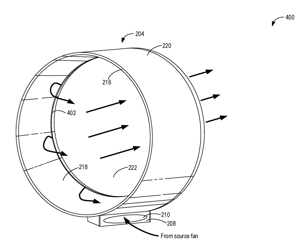
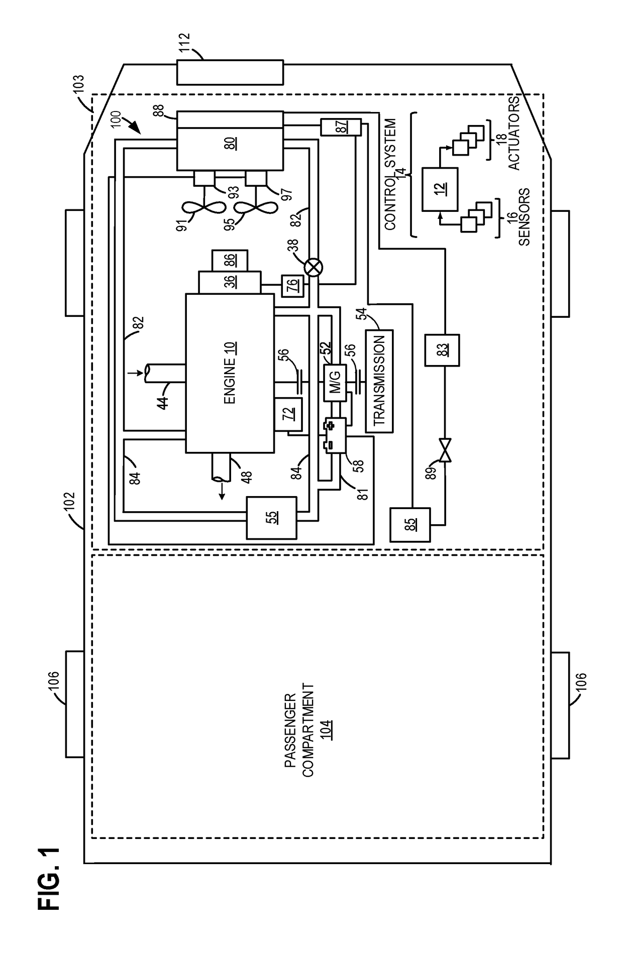
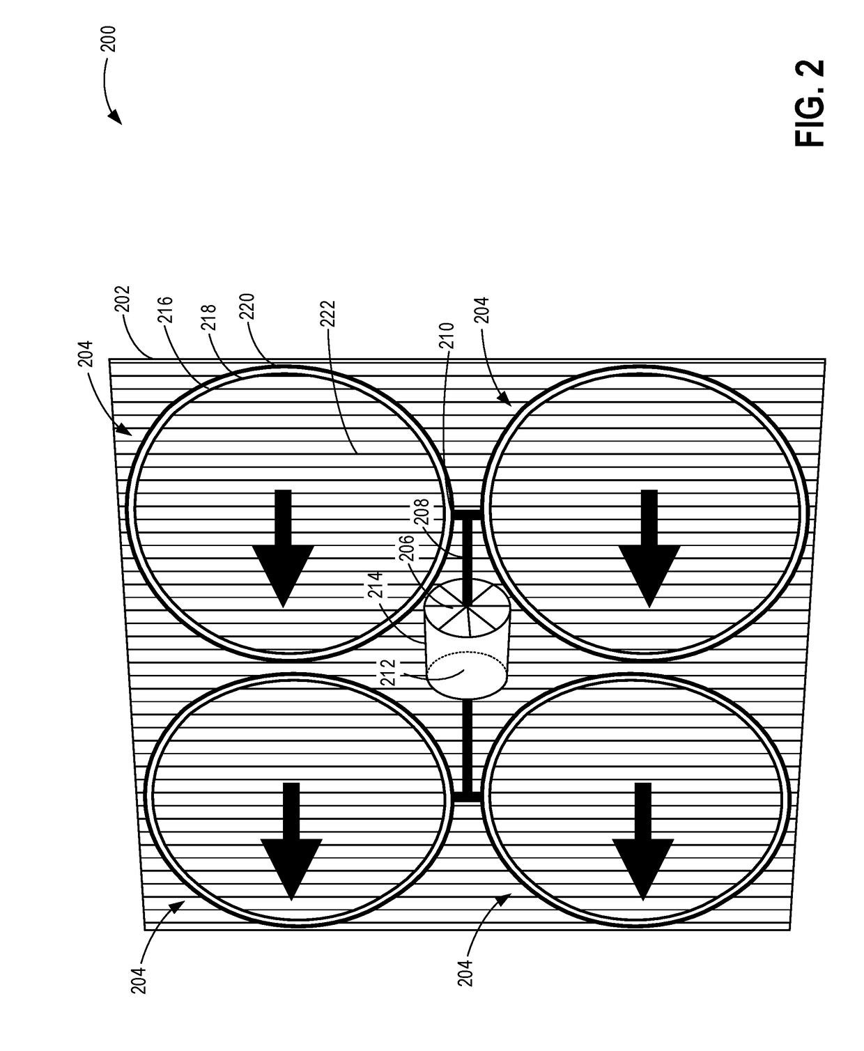
[0018]The following description relates to a bladeless cooling fan for a vehicle cooling system, such as the cooling system of FIG. 1. Example configurations for a bladeless cooling fan having a source fan coupled to a Helmholtz resonator are shown in FIGS. 2-3. Various views of the fan are shown in FIGS. 7-9. An example entrainment disc is shown in FIG. 4. A controller may be configured to perform a routine, such as the example routine of FIG. 5, to operate the cooling fan in accordance with various vehicle cooling demands. For example, the cooling fan may be activated at lower vehicle speeds and deactivated at higher vehicle speeds, such as illustrated in the example graph of FIG. 10. In this way, the cooling fan provides improvements over cooling fans in the prior art, such as the fan shown in FIG. 6 and described below.

[0019]FIG. 1 is a schematic depiction of an example embodiment of a vehicle cooling system 100 in a motor vehicle 102. Vehicle 102 has wheels 106, a passenger com...


PUM


Abstract

Systems and methods are provided for a bladeless radiator cooling fan. In one example, a system may include a plurality of bladeless entrainment discs surrounded by a shroud, each bladeless entrainment disc including a hollow central opening that enables unrestricted ambient airflow through the cooling fan, and a source fan for providing airflow to the bladeless entrainment that is encased by a housing. In this way, airflow through the bladeless radiator cooling fan may be increased, decreasing powered fan usage and decreasing fan noise.

Description

CROSS REFERENCE TO RELATED APPLICATION[0001]The present application claims priority to U.S. Provisional Patent Application No. 62 / 455,461 entitled “Cooling Fans for Engine Cooling System,” filed on Feb. 6, 2017. The entire contents of the above-referenced application are hereby incorporated by reference in their entirety for all purposes.TECHNICAL FIELD[0002]The present application relates to cooling fans that may be used in a vehicle cooling system.BACKGROUND AND SUMMARY[0003]Vehicle cooling systems may include various cooling components such as radiators, cooling fans and blowers, condensers, liquid coolant, etc. An electrically driven engine cooling fan may be powered by an electric motor that is either variable speed or relay controlled. The cooling fan enables engine temperatures to be maintained in a target range. When engine temperatures (or engine coolant temperatures) exceed the target range, the cooling fan is operated to increase airflow through the engine, which carries ...

Claims


Application Information

Patent Timeline
Patent Type & Authority Applications(United States)
IPC IPC(8): F04F5/16F04F5/46F01P5/02
CPCF04F5/16F04F5/46F01P5/02F01P2001/005F04D29/665F01P2005/025F01P11/12F04D25/08
Inventor MARTIN, DOUGLASMILLER, KENNETHDUDAR, AED
Owner FORD GLOBAL TECH LLC
Learn More