Controlling the deceleration of a vehicle

Active Publication Date: 2018-08-09
JAGUAR LAND ROVER LTD
View PDF0 Cites 8 Cited by
  • Summary
  • Abstract
  • Description
  • Claims
  • Application Information

AI Technical Summary

Benefits of technology

The invention prevents or limits the buildup of surface material in front of wheels when a vehicle stops, making it easier for it to move. This happens by using braking that works against the increased drive torque applied to the wheels when the vehicle is stopped. This results in a more consistent level of braking, providing comfort for the vehicle's occupants during braking regardless of the driver's style.

Problems solved by technology

For a vehicle being decelerated to a stop whilst traversing a deformable, low-mu surface, such as, for example, sand, gravel, mud, or wet grass, the effect of the disc “grabbing” the pad and terminating wheel rotation may cause the wheels of the vehicle to skid a short distance and dig into the material forming the surface (e.g., sand, gravel, mud, etc.) as the vehicle comes to a standstill because the surface cannot withstand the friction between the wheels and the surface material required to stop the vehicle.
As a result, the material forming the surface (e.g., sand, mud, gravel, etc.) may build up in front of the vehicle wheels, making it more difficult to subsequently pull away in a composed manner (i.e., because the vehicle must overcome the build-up of material before progressing in a desired manner).
Similarly, when a vehicle is being decelerated to a stop whilst traveling a high-mu surface (e.g., pavement), and both the brake pressure and speed are below certain particular amounts, the friction in the brake system in the final portion of a braking event may result in the vehicle coming to an abrupt stop without skidding (i.e., the friction increases to a point at which the pads “grab” the disc).
In other words, rather that the vehicle speed gradually reducing to zero, it will reduce to a particular speed and then the friction in the braking system, combined with the high friction between the wheels and the high-mu surface, will cause the vehicle to abruptly stop.
As such, rather than slowing to a stop in a smooth, composed manner, the front end of the vehicle may dip or dive downward relative to the back end of the vehicle, resulting in the stopping of the vehicle in an abrupt, uncomposed manner that may be uncomfortable to the passengers in the vehicle.

Method used


Image

  • Controlling the deceleration of a vehicle
  • Controlling the deceleration of a vehicle
  • Controlling the deceleration of a vehicle

Examples


Embodiment Construction

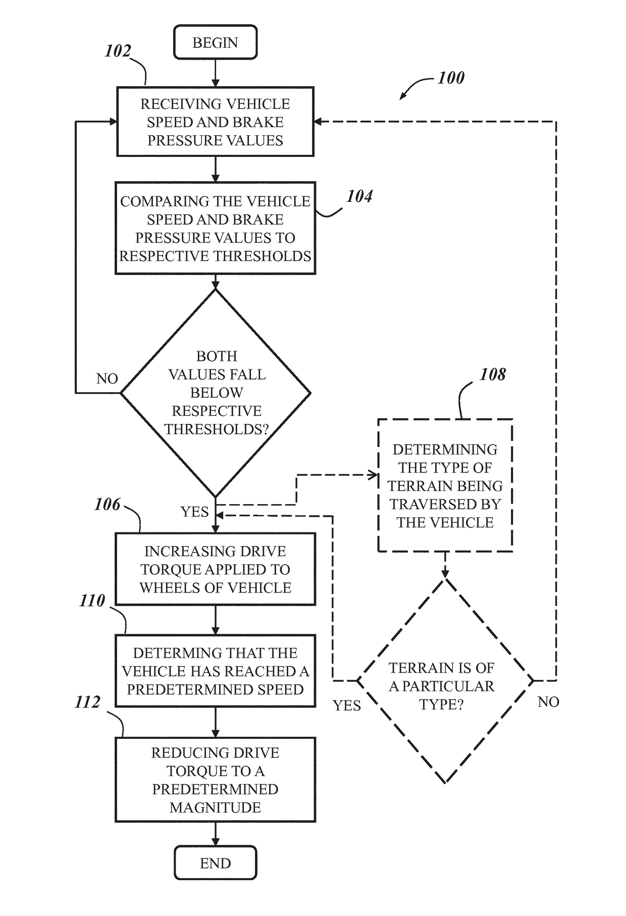
[0019]The system and method described herein may be used to automatically control the deceleration of a vehicle to account for an increase in friction in the vehicle braking system as the vehicle decelerates. In an embodiment, the present system and method receive a signal indicative of a value of the speed of the vehicle and a signal indicative of a value of a brake pressure in the vehicle brake system, compare each of the values to a respective threshold, and when both values fall below the thresholds to which they were compared, command an increase in the drive torque applied to one or more wheels of the vehicle such that the increased drive torque acts against the braking of the vehicle as the vehicle decelerates to a stop or standstill.

[0020]References herein to a block such as a function block are to be understood to include reference to software code for performing the function or action specified in which an output is provided responsive to one or more inputs. The code may b...


PUM


Abstract

A method of controlling the deceleration of a vehicle to account for an increase in friction in the vehicle brake system as the vehicle decelerates. The method comprises receiving a signal indicative of a value of the speed of the vehicle and a signal indicative of a value of a brake pressure in the vehicle brake system. The method further comprises comparing the vehicle speed value and the brake pressure value to respective thresholds. The method still further comprises increasing the drive torque applied to one or more wheels of the vehicle when the vehicle speed value falls below the threshold to which it was compared and the brake pressure value exceeds the threshold to which it was compared, such that the increased drive torque acts against the braking of the vehicle as the vehicle is decelerated to a stop.

Description

TECHNICAL FIELD[0001]The present invention relates to automatic speed control of a vehicle and particularly, but not exclusively, to automatically controlling the deceleration of a vehicle to account for an increase in friction in the vehicle braking system as the vehicle decelerates. Aspects of the invention relate to a method, to a non-transitory computer-readable storage medium, to a system, to a vehicle, and to an electronic controller.BACKGROUND[0002]As a vehicle decelerates to a stop, the friction in the braking system (e.g., between the brake pads and discs) increases as the brake pressure applied to the wheels of the vehicle increases, and thus, the speed of the vehicle decreases. It has been identified that in addition, due to the dynamic characteristics of the forces acting within the brake disc / brake pad arrangement, as the vehicle slows down, at low speeds, and particularly at lower braking pressures the braking effect increases sharply shortly before the vehicle comes t...

Claims


Application Information

Patent Timeline
IPC IPC(8): B60T8/1761B60W10/06B60W10/188B60W30/18B60T8/32
CPCB60T8/1761B60W10/06B60W10/188B60W30/18109B60T8/3275B60T2230/04B60T2270/303B60W2510/182B60W2520/105B60W2710/105B60W2520/10B60W2720/106B60T8/00B60T2210/16B60W10/04B60W30/18B60W30/181B60W30/18172B60W2710/0677B60W2710/0666B60W2720/28B60W2720/30B60W2720/26B60W2520/28B60W2520/26
Inventor KELLY, JAMESARMSTRONG, DAVID
Owner JAGUAR LAND ROVER LTD
Why Eureka
Try Eureka