Casting device for applying a foaming reaction mixture

Inactive Publication Date: 2018-08-09
COVESTRO DEUTSCHLAND AG
View PDF3 Cites 4 Cited by
  • Summary
  • Abstract
  • Description
  • Claims
  • Application Information

AI Technical Summary

Benefits of technology

The invention is a pouring device that reduces the time it takes for a reaction mixture to flow through the device. This is achieved by designing the duct cross-section to become smaller as the distance from the feed port increases. The feed duct can extend on both sides away from the feed port and has its largest cross-section at the connection point to the feed port. The outlet slot has a width that is formed constantly over its entire two-dimensional extent and can have small local deviations in width. The feed duct is curved, with the highest height of the slot space occurring at the beginning of the feed duct. The plurality of individual slot spaces can be arranged in a way that the outlet slot is continuous and straight or bent. The reaction mixture can be gas loaded to prevent clogging of the slot space. Overall, the invention reduces the time it takes for a reaction mixture to flow through the device and improves the control of foaming.

Problems solved by technology

The consequence is uneven foaming of the reaction mixture with multiple foam fronts and in the cured state the polyurethane foam core has a non-homogeneous texture.
Turbulence forms, with bubbles and voids, wherein the cell orientation of the foam is generally also not uniform.
This reduces the quality of the foam structure, and may result in too little adhesion on the inside of the facing layers, leading to reduced composite element quality, in particular with regard to mechanical and / or thermal characteristics, surface quality and / or compressive strength.
It is not sufficient, for this purpose, to generate the same volumetric flow rate at each position of the outlet slot over the length thereof in the transverse direction, since the transit time of the reaction mixture through the pouring device is likewise a decisive factor.
A further disadvantage consists in the fact that the triangular shape does not allow a uniform outflow speed to be established for outflow of the reaction mixture out of the outlet slot, since in the peripheral region of the triangular structure of the slot spaces a higher pressure drop prevails than in the middle due to the longer flow path.

Method used


Image

  • Casting device for applying a foaming reaction mixture
  • Casting device for applying a foaming reaction mixture
  • Casting device for applying a foaming reaction mixture

Examples


Embodiment Construction

[0029]Further measures which improve the invention are described in greater detail below with reference to the figures, together with the description of a preferred exemplary embodiment of the invention. In the figures:

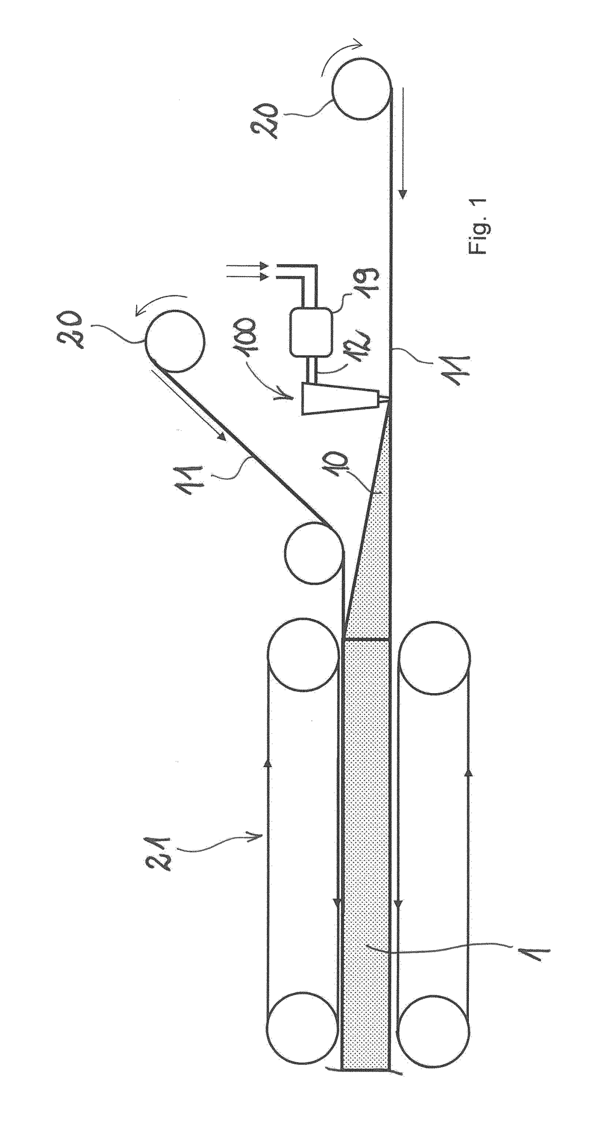
[0030]FIG. 1 is an overall view of the installation with a pouring device and facing layer feed and a double belt conveying installation,

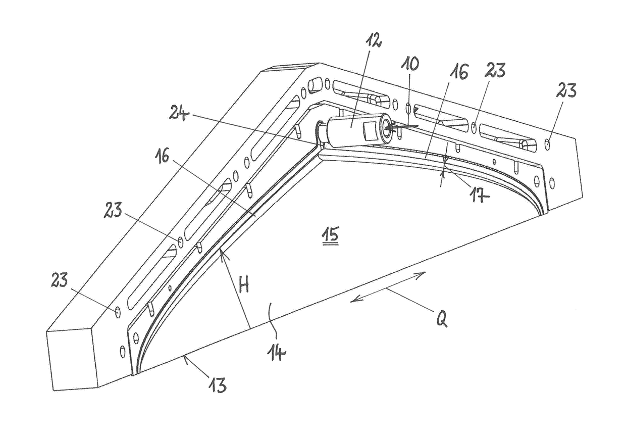
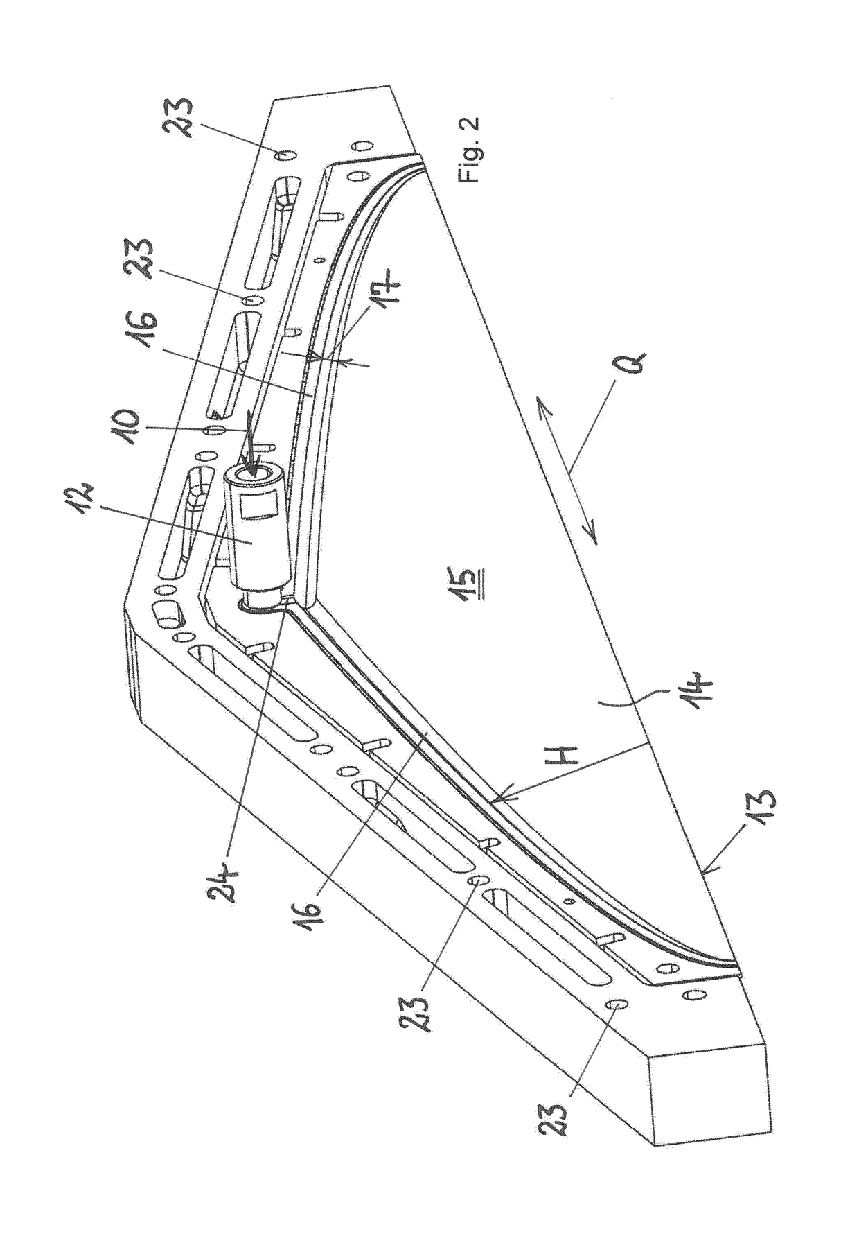
[0031]FIG. 2 is a perspective representation of a slot plate 14 from that side which two-dimensionally delimits the slot space,

[0032]FIG. 3 a transversely sectional view of the pouring device with two slot plates arranged on one another, forming the slot space between the slot plates,

[0033]FIG. 3a shows a modified embodiment of the outlet slot with slot lips formed thereon,

[0034]FIG. 4 is a perspective view of a continuous slot plate, which forms a plurality of individual pouring devices and

[0035]FIG. 5 is a perspective view of part of a pouring device with adjusting means arranged on the slot plates.

[0036]FIG. 1 shows a schematic vi...


PUM

PropertyMeasurementUnit
Lengthaaaaaaaaaa
Volumeaaaaaaaaaa
Widthaaaaaaaaaa

Abstract

The invention relates to a casting device for applying a foaming reaction mixture, to at least a partial width of a cover layer, wherein the casting device comprises: a supply connection for feeding in the reaction mixture; at least one exit slit extending in a transverse direction for the exiting of the reaction mixture; two slit plates arranged opposite one another, wherein a slit space extends between the slit plates in a vertical direction above the exit slit. A supply channel connected to the supply connection is formed between the slit plates, which closes off the slit space above the exit slit in the vertical direction The supply channel has a channel cross-section, the main dimension of which is larger that the width of the slit space. The reaction mixture can be introduced into the slit space to distribute the reaction mixture over the length of the supply channel.

Description

[0001]The invention relates to a pouring device for applying a foaming reaction mixture at least comprising polyol and isocyanate over at least part of the width of a facing layer, in particular for producing a composite element, wherein the pouring device comprises a feed port for feeding in the reaction mixture and forms an outlet slot extending in a transverse direction for discharge of the reaction mixture, and wherein the pouring device comprises two opposingly arranged slot plates, wherein a slot space between the slot plates extends in a vertical direction above the outlet slot.BACKGROUND OF THE INVENTION[0002]EP 2 216 156 A1 discloses a pouring device for applying a foaming reaction mixture comprising polyol and isocyanate to produce composite elements. Composite elements comprise at least one facing layer and for the most part two facing layers guided parallel to one another, and the reaction mixture is applied to one of the facing layers, in particular to the inside of a l...

Claims


Application Information

Patent Timeline
IPC IPC(8): B29C44/46B05C5/02B29C44/50B29C44/34
CPCB29C44/461B05C5/0254B29C44/505B29C44/3402B29K2075/00B29K2105/04
Inventor BRUNING, DIRKSYMANNEK, ACHIMFRANKEN, KLAUSSCHLEIERMACHER, STEPHENHERWEG, THOMAS
Owner COVESTRO DEUTSCHLAND AG
Why Eureka
Try Eureka