
Ventilator with a synchronicity index

a technology of synchronicity index and ventilator, applied in the field of ventilator, can solve the problems of unsatisfactory adaptation of ventilation pressure, lack of synchronicity between pressure control and patient respiration, and restricted ventilation success, so as to reduce increase the sensitivity of expiration trigger, and increase the sensitivity of inspiration trigger

Pending Publication Date: 2018-08-09
LOWENSTEIN MEDICAL TECH SA
View PDF7 Cites 7 Cited by
  • Summary
  • Abstract
  • Description
  • Claims
  • Application Information

AI Technical Summary

Benefits of technology

The ventilator described in this patent offers several benefits, including improved monitoring of patient synchronization with ventilation. This allows for simpler and more cost-efficient control of ventilation, and helps quickly identify and fix any faults or problems that may occur during ventilation. Additionally, the ventilator can automatically adjust settings to improve ventilation quality, such as lowering the trigger threshold for premature targets or increasing the duration of mandatory exhalations.

Problems solved by technology

If the ventilation success is unsatisfactory, a note regarding an unwanted system leak is usually output as a possible source of error in current ventilators.
However, a particularly decisive cause for restricted ventilation success can often also be found in a lack of synchronicity between pressure control and patient respiration.
Here, as a rule, the ventilation pressure is not ideally adapted in time to the respective respiratory phase of the patient.
The lack of synchronicity may lead to the patient having to muster increased and, as a rule, very straining respiratory exertion in order to be able to follow the pressure control that has not been adapted in time.
As a result, the ventilation success may be significantly impaired.
However, identifying a lack of synchronicity is very time-consuming as a rule, and the staff require high levels of specialist knowledge.
The latter is a great disadvantage, particularly in the case of patients with home ventilation, since large amounts of data have to be transferred and evaluated in this case.

Method used


Image

  • Ventilator with a synchronicity index
  • Ventilator with a synchronicity index
  • Ventilator with a synchronicity index

Examples


Embodiment Construction

[0100]The particulars shown herein are by way of example and for purposes of illustrative discussion of the embodiments of the present invention only and are presented in the cause of providing what is believed to be the most useful and readily understood description of the principles and conceptual aspects of the present invention. In this regard, no attempt is made to show details of the present invention in more detail than is necessary for the fundamental understanding of the present invention, the description in combination with the drawings making apparent to those of skill in the art how the several forms of the present invention may be embodied in practice.

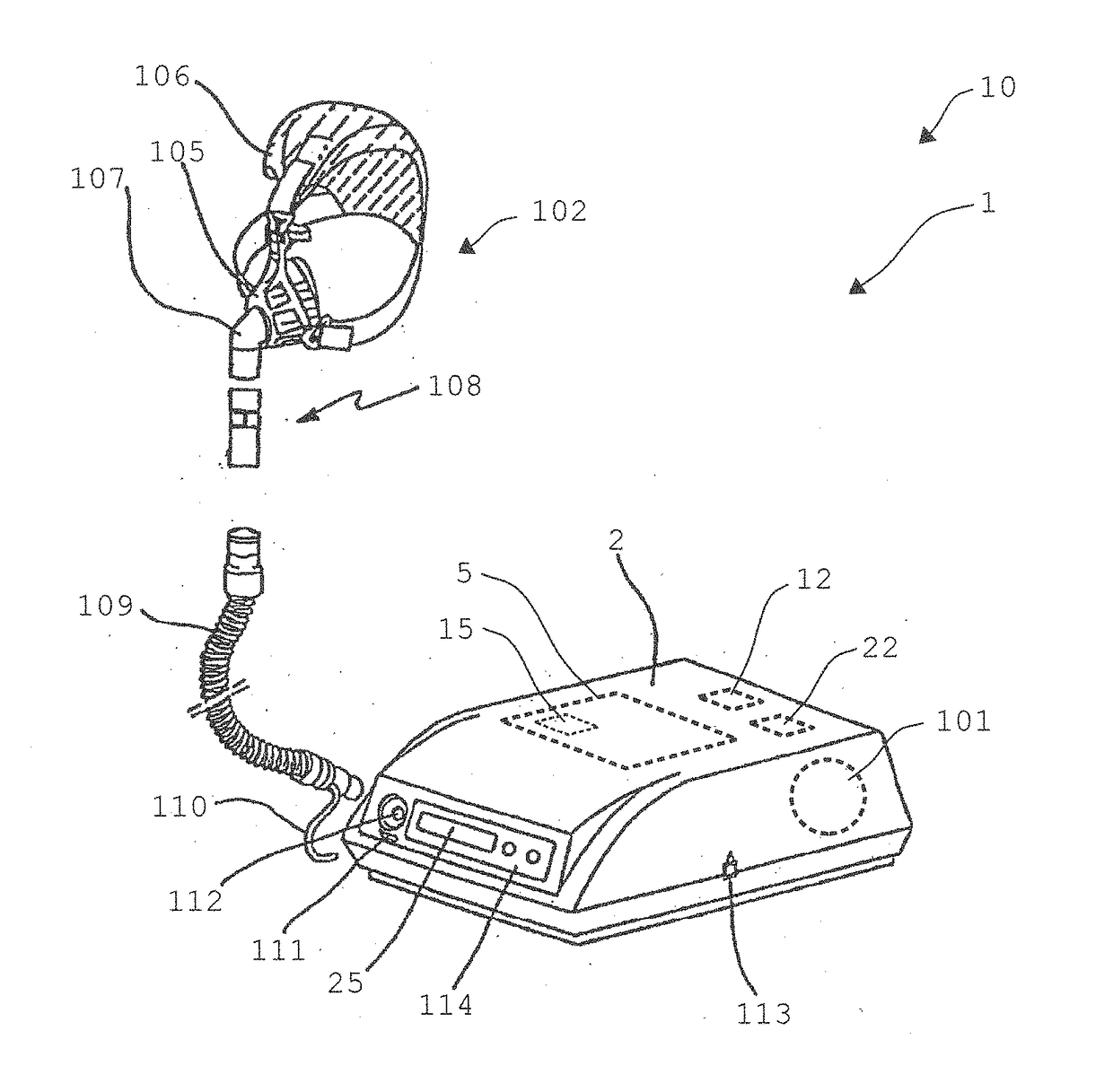
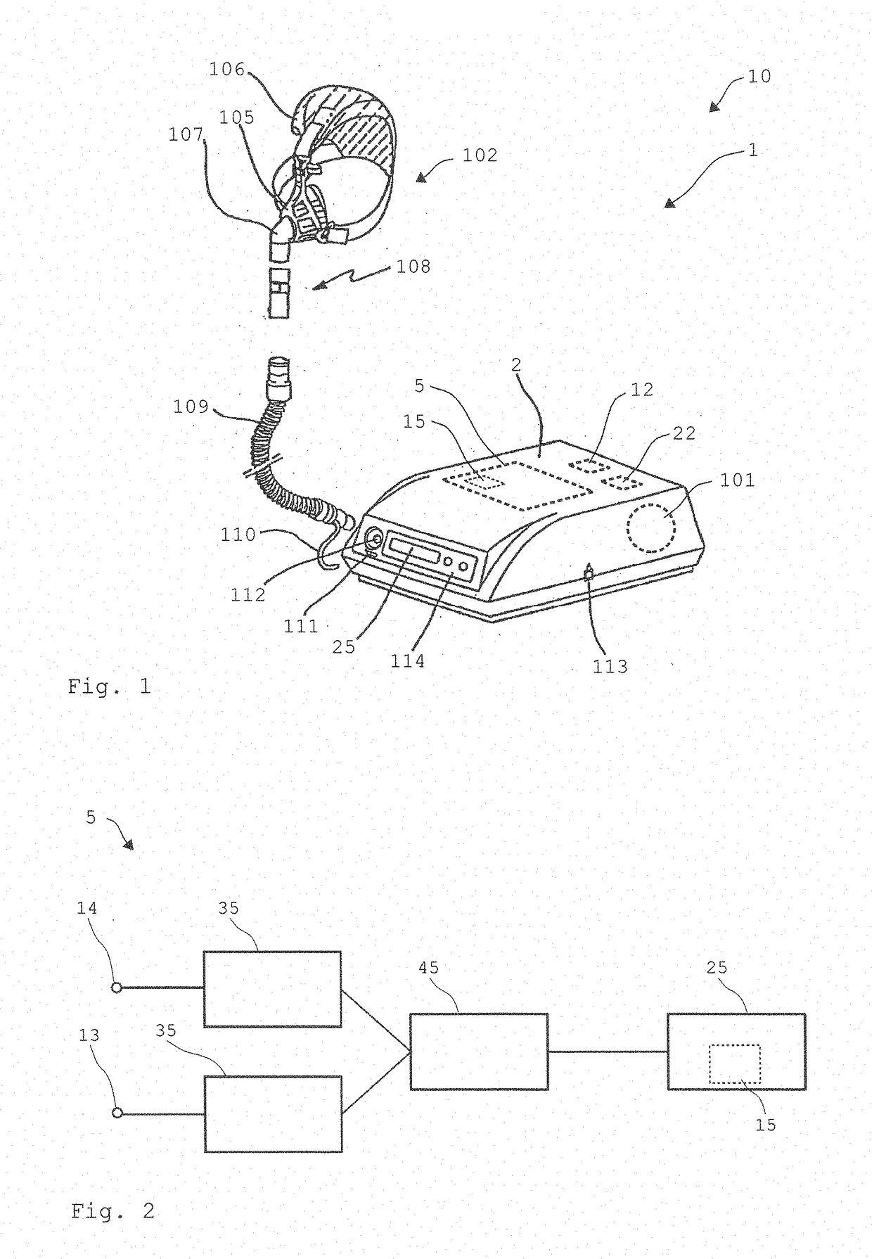
[0101]FIG. 1 shows a ventilator 1 according to the invention, which is embodied here as a home ventilator or as a sleep therapy appliance. However, the ventilator 1 may also be embodied as a clinical ventilator 1. The ventilator 1 is suitable and designed for carrying out the method according to the invention.

[0102]Operati...


PUM


Abstract

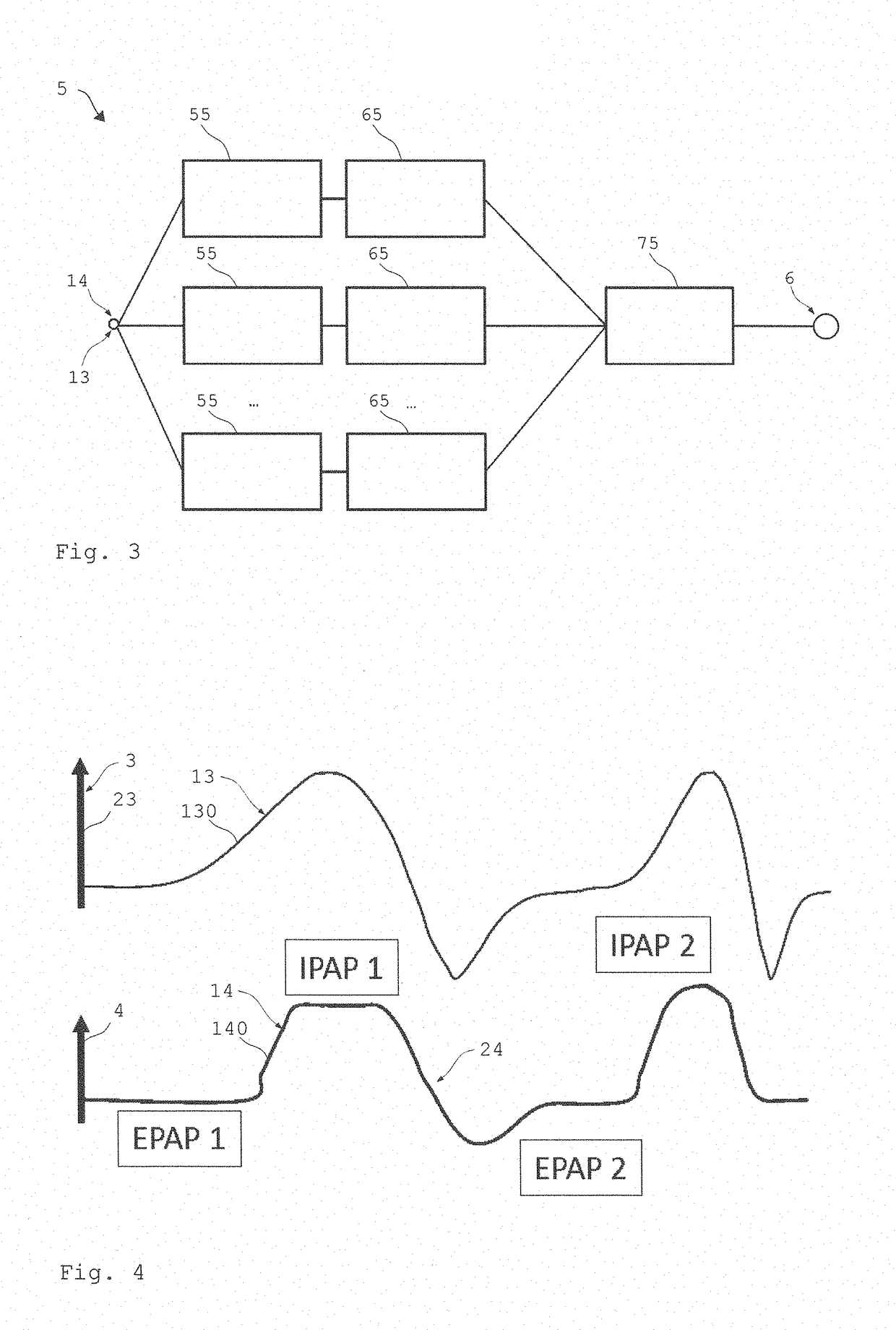
Disclosed is a ventilator comprising a ventilation device which produces a respiratory gas flow for ventilating at least one patient and sets the respiratory gas flow to at least one ventilation pressure depending on at least one respiratory phase of the patient. Provision is made of a monitoring device which is suitable and configured for monitoring a synchronicity between respiratory phase and target ventilation pressure and, to this end, capturing a characteristic signal for the ventilation pressure and a characteristic signal for the respiratory phase of the patient and comparing the two signals to one another and determining a characteristic for the synchronicity on the basis of the comparison.

Description

CROSS-REFERENCE TO RELATED APPLICATIONS[0001]The present application claims priority under 35 U.S.C. § 119 of German Patent Application No. 102017000980.5, filed Feb. 3, 2017, the entire disclosure of which is expressly incorporated by reference herein.BACKGROUND OF THE INVENTION1. Field of the Invention[0002]The present invention relates to a ventilator having at least one ventilation device for producing a respiratory gas flow for ventilating at least one patient. The respiratory gas flow can be set to at least one ventilation pressure depending on at least one respiratory phase of the patient.2. Discussion of Background Information[0003]As a rule, ventilators identify a ventilation success by measuring tidal volume, tidal air, respiratory frequency and, sometimes, by measuring respiratory gases or blood gases as well. If the ventilation success is unsatisfactory, a note regarding an unwanted system leak is usually output as a possible source of error in current ventilators.[0004]...

Claims


Application Information

Patent Timeline
Patent Type & Authority Applications(United States)
IPC IPC(8): A61M16/00A61M16/06
CPCA61M16/024A61M16/0003A61M16/0683A61M2016/0018A61M2016/0027A61M2205/3303A61M2205/3334A61M16/0066A61M16/06A61M2016/0021A61M2016/0036A61M2205/18A61M2205/3331A61M2205/502A61M2205/52A61M2205/581A61M2205/583A61M2230/04A61M2230/10A61M2230/205A61M2230/40A61M2230/60A61M2230/63A61M16/0858A61M16/026
Inventor SCHWAIBOLD, MATTHIAS
Owner LOWENSTEIN MEDICAL TECH SA
Learn More