
Bend-resistant mini optical fiber and manufacturing method thereof

Inactive Publication Date: 2018-08-02
ZHONGTIAN TECH FIBER OPTICS
View PDF2 Cites 1 Cited by
  • Summary
  • Abstract
  • Description
  • Claims
  • Application Information

AI Technical Summary

Benefits of technology

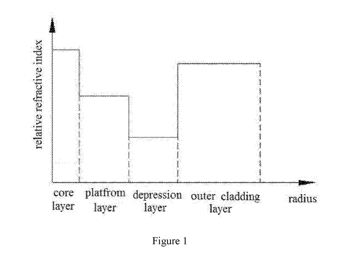
The present invention provides a narrow-diameter bending resistant optical fiber with reduced space resources and ultra-low bending loss performance. The fiber has a unique structure that includes a core layer, a platform layer, a depression layer, an outer cladding layer, and a coating layer, with the relative refractive index and radius of each layer being reasonably controlled. The cutoff wavelength is maintained in a relatively stable range, which reduces macrobending loss of the optical fiber. The diameter of the fiber is only 80 μm, which saves resources and increases strength. The bend-resistant mini optical fiber meets the service life of more than 30 years. The manufacturing process includes controlling the refractive index and radius of each layer, employing an automatic temperature and tension monitoring procedure, and setting up a calculation model to calculate the service life of the optical fiber. The coating pressure and drawing speed are set within appropriate ranges to ensure good optical fiber quality. The curing and drying process is quick and the product quality is good.

Problems solved by technology

The traditional single-mode optical fiber can not meet the space requirements of some devices and has a relatively large blending loss.

Method used


Image

  • Bend-resistant mini optical fiber and manufacturing method thereof
  • Bend-resistant mini optical fiber and manufacturing method thereof
  • Bend-resistant mini optical fiber and manufacturing method thereof

Examples


embodiment 1

[0028]The present invention further discloses a manufacturing method of a bend-resistant mini optical fiber, the manufacturing method is as follows:

[0029](1) The outer cladding layer, the depression layer, the platform layer and the core layer are successively deposited by modified chemical vapor deposition method;

[0030](2) The deposited tube is placed on heat shrinking machine and fused and shrank into solid preform;

[0031](3) The preform is fixed on the drawing tower and drawn into optical fiber at a temperature of 2150° C.;

[0032](4) Installing the coating mold for drawing, the coating pressure is controlled between 0.01-0.02 Mpa, the drawing speed is 500-800 m / min, cutting the optical fiber after drawing;

[0033](5) Setting the curing distance of drawing tower as 2 m -4 m, and curing and drying the optical fiber in curing oven; the total power of the curing oven is 18000-24000W.

[0034](6) After curing, the optical fiber is wound on an automatic wire take-up device, and the optical fi...

embodiment 2

[0037]A manufacturing method of a bend-resistant mini optical fiber is shown as below:

[0038](1) The outer cladding layer, the depression layer, the platform layer and the core layer are successively deposited by modified chemical vapor deposition method;

[0039](2) The deposited tube is placed on heat shrinking machine and fused and shrank into solid preform;

[0040](3) The preform is fixed on the drawing tower and drawn into optical fiber at a temperature of 2150° C.;

[0041](4) Installing the coating mold for drawing, wherein the coating pressure is controlled between 0.02-0.025 Mpa, the drawing speed is 800-1500 m / min, cutting the optical fiber after drawing;

[0042](5) Setting the curing distance of drawing tower as 2 m -4 m, and curing and drying the optical fiber in curing oven; wherein the total power of the curing oven is 18000-24000W.

[0043](6) After curing, the optical fiber is wound on an automatic wire take-up device, and the optical fiber drawing cone is designed. The angle of t...

embodiment 3

[0046]A manufacturing method of a bend-resistant mini optical fiber is shown as below:

[0047](1) The outer cladding layer, the depression layer, the platform layer and the core layer are successively deposited by modified chemical vapor deposition method;

[0048](2) The deposited tube is placed on a heat shrinking machine and fused and shrank into solid preform;

[0049](3) The preform is fixed on the drawing tower and drawn into optical fiber at a temperature of 2150° C.;

[0050](4) Installing the coating mold for drawing, wherein the coating pressure is controlled between 0.025-0.035 Mpa, the drawing speed is 1500-2000m / min, cutting the optical fiber after drawing;

[0051](5) Setting the curing distance of drawing tower as 2 m -4 m, and curing and drying the optical fiber in curing oven; wherein the total power of the curing oven is 18000-24000W.

[0052](6) After curing, the optical fiber is wound on an automatic wire take-up device, and the optical fiber drawing cone is designed. The angle o...


PUM

PropertyMeasurementUnit
Temperatureaaaaaaaaaa
Lengthaaaaaaaaaa
Lengthaaaaaaaaaa

Abstract

A bend-resistant mini optical fiber and manufacturing method thereof, first, preparing a preform via a modified chemical vapor deposition process, and manufacturing an optical fiber via drawing at a certain temperature. The advantageous of the present invention are as following, the bend-resistant mini optical fiber is primarily formed by a core layer, a platform layer, a depression layer, an outer cladding layer and a coating layer, and the relative refractive index and radius of each of the layers is reasonably controlled; and a cutoff wavelength is effectively controlled by employing an automatic temperature and tension monitoring procedure during the drawing process, such that the cutoff wavelength and a mode field diameter are maintained in a relatively stable range, and the cutoff wavelength is adjusted upward while the mode field diameter remains stable, thus facilitating a decrease of bend loss of the optical fiber.

Description

CROSS REFERENCE TO RELATED APPLICATIONS[0001]This application is the national phase entry of International Application No. PCT / CN2015 / 099425, filed on Dec. 29, 2015, which is based upon and claims priority to Chinese Application No.201510542224.X, filed on Aug. 31, 2015, the entire contents of which are incorporated herein by reference.TECHNICAL FIELD[0002]The present invention relates to a bend-resistant mini optical fiber and manufacturing method thereof, belonging to a field of optical fiber transmission technology.BACKGROUND[0003]With China's large-scale promotion of Triple Play and Broadband China strategy, will come a new round of growth of the construction of 4G networks and data centers. With the expansion of broadband services, the construction of communication networks has developed from core networks to access networks and FTTH (fiber to the home, FTTH). The optical fibers built by FTTH are located in crowded and narrow channels and are repeatedly bent and placed on the c...

Claims


Application Information

Patent Timeline
IPC IPC(8): G02B6/036G02B6/02
CPCG02B6/03638G02B6/02395G02B6/02004C03B37/018C03B37/025G02B6/0365C03B2203/22C03C25/104C03C25/106
Inventor CAO, SHANSHANLIU, ZHIZHONGHU, JIGANGWANG, ZHENZHANG, HAITAOZHOU, HUI
Owner ZHONGTIAN TECH FIBER OPTICS
Learn More