
Viewing angle switchable display apparatus

a display apparatus and viewing angle technology, applied in the field of viewing angle switchable display apparatus, can solve the problems of user manual placement/removal of the display apparatus, leakage of confidential information, inconvenience in use, etc., and achieve the effect of expanding the viewing angl

Active Publication Date: 2018-07-26
CORETRONIC
View PDF7 Cites 88 Cited by
  • Summary
  • Abstract
  • Description
  • Claims
  • Application Information

AI Technical Summary

Benefits of technology

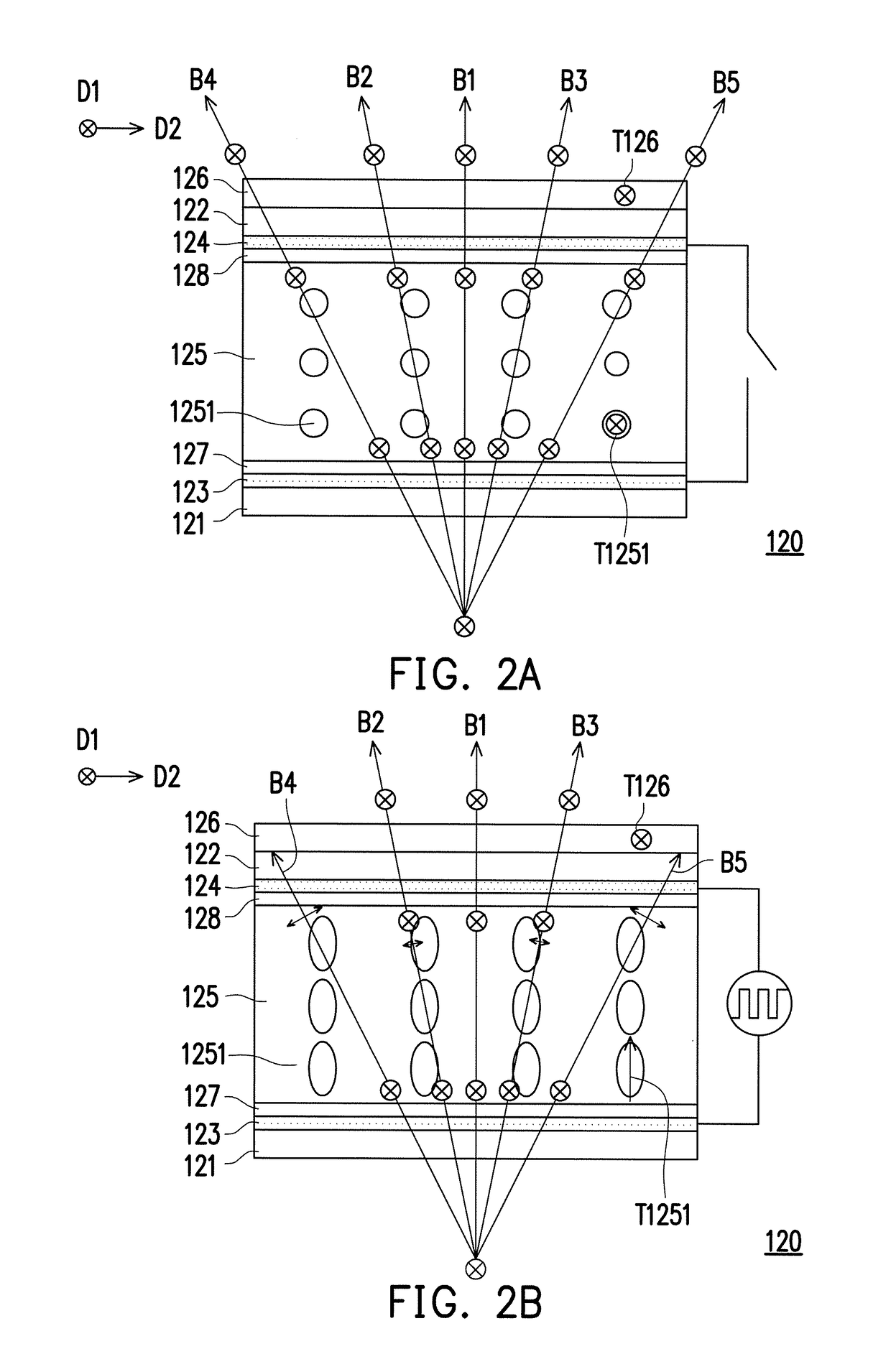
The invention is a display apparatus that allows for switching between an anti-peep mode and a share mode. The anti-peep mode prevents light beams from being scattered when passing through the display, while the share mode scatters the light beams to enlarge the viewing angle. The viewer can choose to see the displayed image or information shared by another viewer. The technical effect of this invention is to provide a display apparatus that allows for both anti-peep and share modes, providing flexibility and improved viewing experience for the viewer.

Problems solved by technology

However, in some situations or occasions (for example, when a private web page or confidential information is browsed in public, or a password is input), the wide viewing angle display effect may cause confidential information to be peeped by others which leads to leak of the confidential information.
It causes inconvenience in use that users have to manually place / remove the LCF.

Method used


Image

  • Viewing angle switchable display apparatus
  • Viewing angle switchable display apparatus
  • Viewing angle switchable display apparatus

Examples


Embodiment Construction

[0019]In the following detailed description of the preferred embodiments, reference is made to the accompanying drawings which form a part hereof, and in which are shown by way of illustration specific embodiments in which the invention may be practiced. In this regard, directional terminology, such as “top,”“bottom,”“front,”“back,” etc., is used with reference to the orientation of the Figure(s) being described. The components of the invention can be positioned in a number of different orientations. As such, the directional terminology is used for purposes of illustration and is in no way limiting. On the other hand, the drawings are only schematic and the sizes of components may be exaggerated for clarity. It is to be understood that other embodiments may be utilized and structural changes may be made without departing from the scope of the invention. Also, it is to be understood that the phraseology and terminology used herein are for the purpose of description and should not be ...


PUM

PropertyMeasurementUnit
reflectivityaaaaaaaaaa
light transmittanceaaaaaaaaaa

Abstract

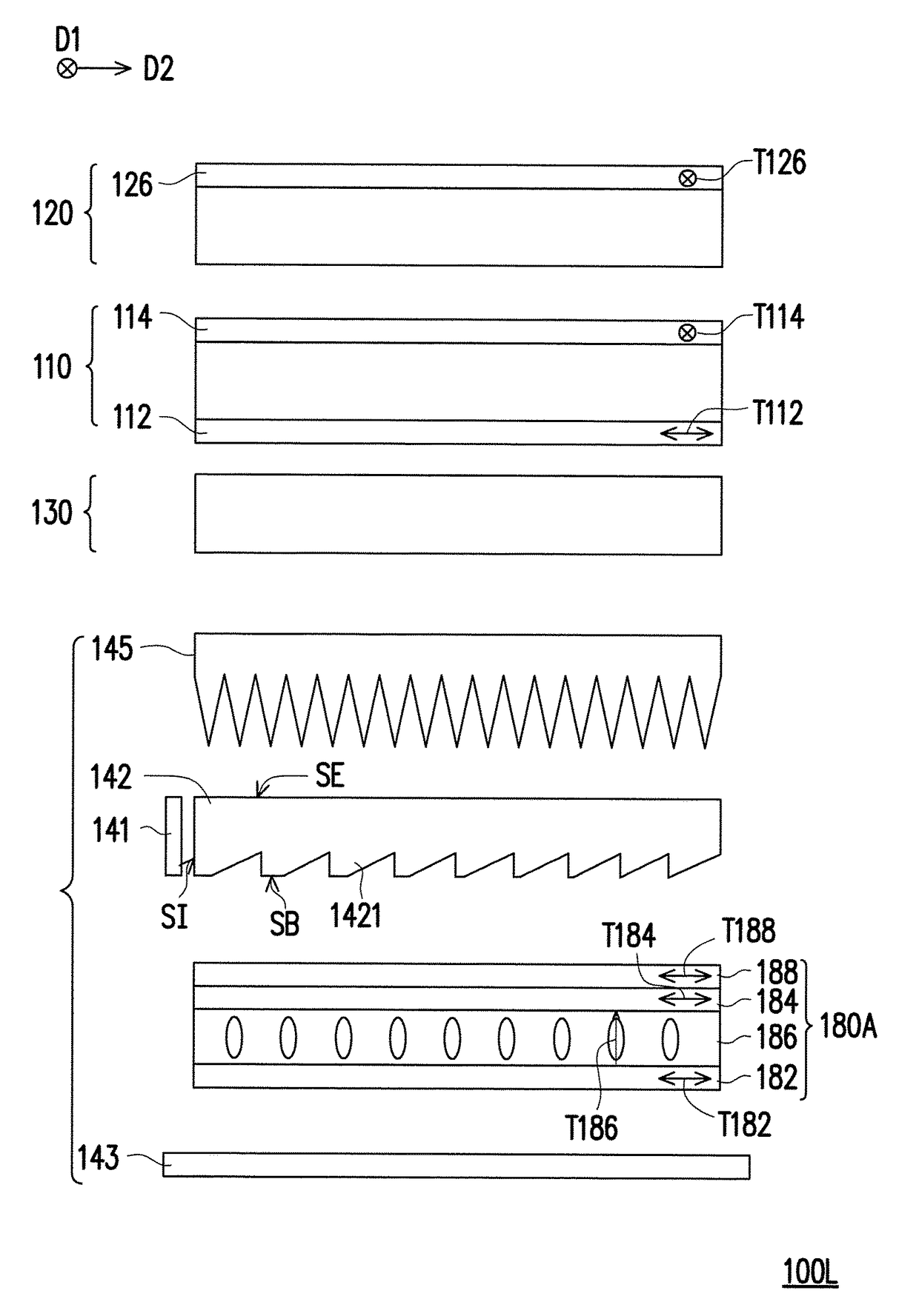
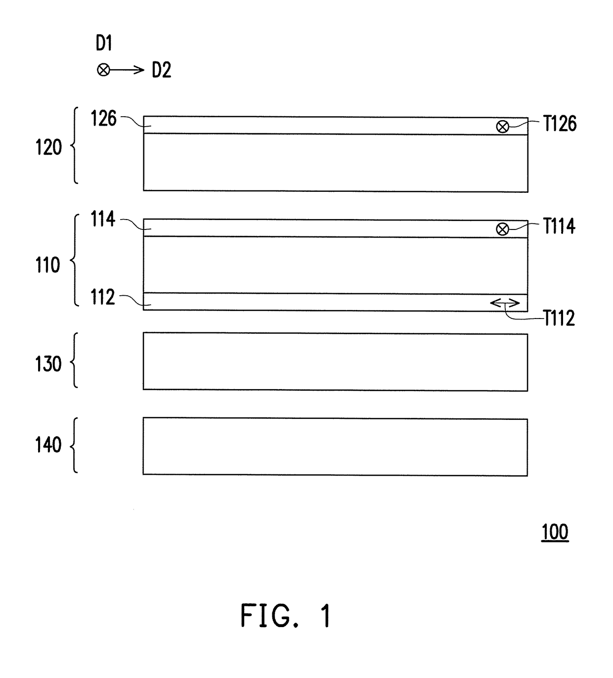
A viewing angle switchable display apparatus including a display panel, an electrically controlled viewing angle switching device, an electrically controlled light scattering switching device, and a backlight module is provided. The electrically controlled viewing angle switching device includes two first transparent substrates, two first transparent conductive layers, a liquid crystal layer, and a first polarizer located on a side of the electrically controlled viewing angle switching device which is far away from the display panel. The liquid crystal layer includes liquid crystal molecules, and optical axes of the liquid crystal molecules are parallel or perpendicular to a transmission axis of the first polarizer. The electrically controlled light scattering switching device is located between the display panel and the backlight module and includes two second transparent substrates, two second transparent conductive layers, and an electronically controlled polymer material layer.

Description

CROSS-REFERENCE TO RELATED APPLICATION[0001]This application claims the priority benefit of China application serial no. 201710060681.4, filed on Jan. 25, 2017. The entirety of the above-mentioned patent application is hereby incorporated by reference herein and made a part of this specification.BACKGROUNDField of the Invention[0002]The invention relates to a display apparatus and more particularly, to a viewing angle switchable display apparatus.Description of Related Art[0003]Generally, a display apparatus offers a wide viewing angle display effect in order to allow multiple viewers to view displayed images together. However, in some situations or occasions (for example, when a private web page or confidential information is browsed in public, or a password is input), the wide viewing angle display effect may cause confidential information to be peeped by others which leads to leak of the confidential information. In order to satisfy anti-peep demands, a general method is to place...

Claims


Application Information

Patent Timeline
Patent Type & Authority Applications(United States)
IPC IPC(8): G02F1/13G02F1/1335G02F1/1333G02F1/1334G02F1/137F21V8/00
CPCG02F1/1323G02F1/133528G02F1/13338G02F1/1334G02F1/137G02B6/0053G02B6/0055G02B6/0038G02B6/0056G02F2001/133302G02F2001/13345G02F1/133536G02F1/13363G02F1/133504G02F1/133606G02F1/13476G02F1/13345G02F1/133302
Inventor FANG, CHONG-YANGWANG, WEN-CHUNCHEN, PING-YENGHSU, HSIUNG-CHUNLEE, CHIEN-HUI
Owner CORETRONIC
Learn More