
Structure of self-drilling screw

Inactive Publication Date: 2018-07-26
CHAO YING CHIN
View PDF8 Cites 1 Cited by
  • Summary
  • Abstract
  • Description
  • Claims
  • Application Information

AI Technical Summary

Benefits of technology

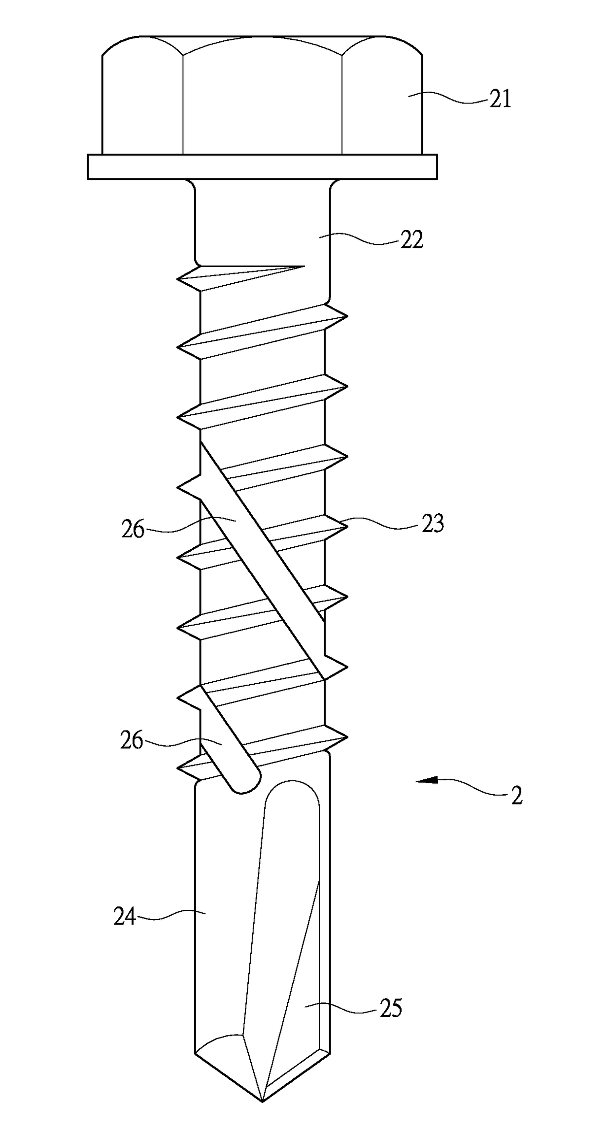
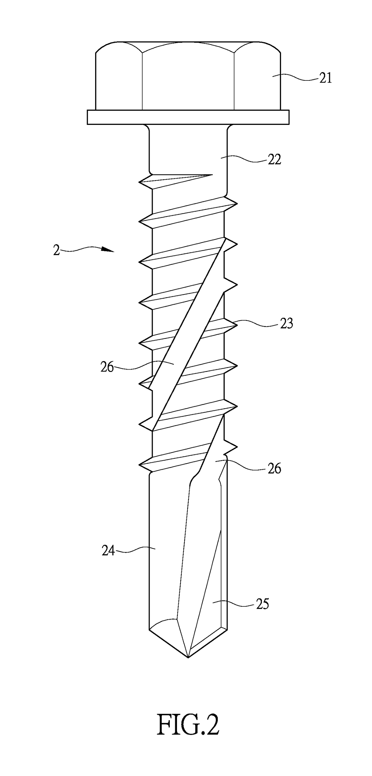
The present invention aims to improve the operation of a screw by introducing a second chip removal groove on the shank of the screw, which can be connected or not connected to the first chip removal groove on the drilling tip section. This results in improved chip removal, reduced screw-in torque, and improved operation quality, saving labor and time.

Problems solved by technology

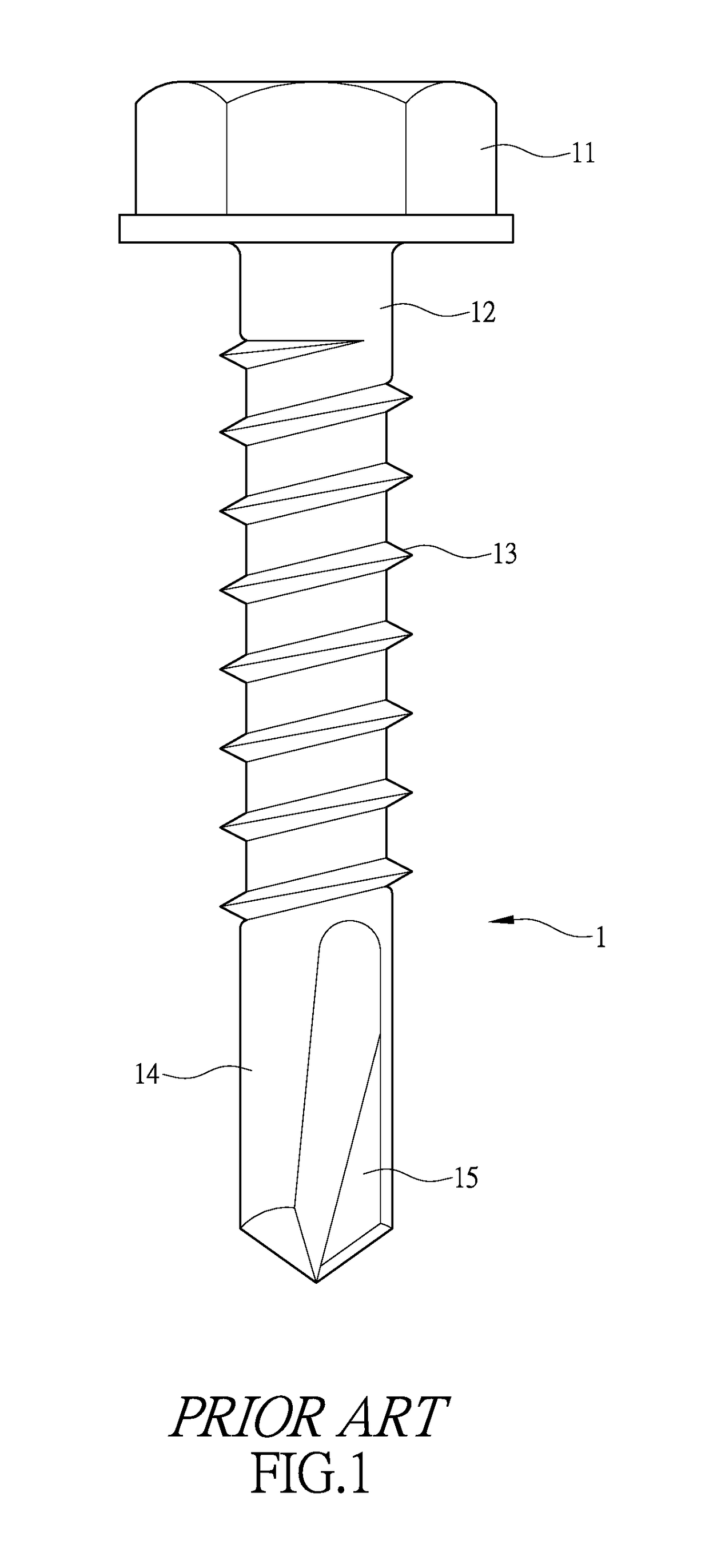
This cause undesired limitation to the performance of cutting and chip removal of the screw 1.
Thus, it is a challenge of the screw manufacturers to provide a structure of a self-drilling screw that ensures desired performance of cutting and chip removal during an operation of drilling, cutting, and screwing in of the screw 1 and also helps reduce frictional torque generated during an operation of screwing and smoothen removal of chips.

Method used


Image

  • Structure of self-drilling screw
  • Structure of self-drilling screw
  • Structure of self-drilling screw

Examples


Embodiment Construction

[0019]The following descriptions are exemplary embodiments only, and are not intended to limit the scope, applicability or configuration of the invention in any way. Rather, the following description provides a convenient illustration for implementing exemplary embodiments of the invention. Various changes to the described embodiments may be made in the function and arrangement of the elements described without departing from the scope of the invention as set forth in the appended claims.

[0020]As shown in FIG. 2, the present invention provides a screw 2, which comprises a screw head 21 and a shank 22 extending downward from the screw head 21. The shank 22 has an outer circumferential surface, which is provided with a thread 23 circumferentially extending around the shank. The shank 22 has a lower end forming a drilling tip section 24. The thread 23 is extended into or is not extended into the drilling tip section 24, this being determined according to the needs or uses of a user. Th...


PUM

PropertyMeasurementUnit
Timeaaaaaaaaaa
Structureaaaaaaaaaa

Abstract

A structure of a self-drilling screw is disclosed. The screw includes a screw head and a shank extending downward from the screw head. The shank has an outer circumferential surface, around which a thread is circumferentially formed. The shank has a lower end forming a drilling tip section. The thread is extended or not extended into the drilling tip section. The drilling tip section is formed with at least one first chip removal groove. The first chip removal groove has an upper end and at least one second chip removal groove is arranged to extend from the upper end along the shank in a direction toward the screw head.

Description

(a) TECHNICAL FIELD OF THE INVENTION[0001]The present invention relates generally to a structure of self-drilling screw, and more particularly to a self-drilling screw structure that improves the capability of the screw for chip removal in operations of cutting, tapping, and drilling into a depth and also helps reduces a torque of the screw during screwing in to thereby achieve effects of saving labor and time in conducting an operation and thus enhance quality of operation conducted with the screw.(b) DESCRIPTION OF THE PRIOR ART[0002]A self-drilling screw is generally used to provide connection between metallic workpiece, wooden workpiece, or metal and wooden workpieces so that workpieces can be fast fastened together by means of the capability of drilling and taping of the screw.[0003]As shown in FIG. 1, a screw 1 comprises a screw head 11 and a shank 12 extending downward from the screw head 11. The shank 12 has a circumferential surface that is formed with a thread 13 helically...

Claims


Application Information

Patent Timeline
IPC IPC(8): F16B25/10F16B25/00
CPCF16B25/103F16B25/0084F16B25/0057F16B25/0068F16B25/0015F16B25/0078
Inventor CHAO, YING-CHIN
Owner CHAO YING CHIN
Learn More