
Magnetic Switch Controlled Circuit for Electrical Appliance

a technology of magnetic switch and control circuit, which is applied in the direction of space heating and ventilation control system, lighting and heating apparatus, heating types, etc., can solve the problems of mechanical wear and tear inability to function at all, and bulky size of conventional mechanical switches, so as to prevent undesirable damage to electrical appliances

Active Publication Date: 2018-07-05
SITU HUA FU
View PDF8 Cites 6 Cited by
  • Summary
  • Abstract
  • Description
  • Claims
  • Application Information

AI Technical Summary

Benefits of technology

The present invention provides a circuit that uses a magnetic switch to control the output of a relay. This circuit allows the switch to turn off after a certain period of time, preventing damage to the electrical appliance. The technical effect of this invention is to provide a safer and more effective way to control the output of a relay.

Problems solved by technology

A conventional mechanical switch is usually bulky in size, and must be mounted on an object through some sorts of connectors or other mechanical tools.
As a result, when the mechanical switch was improperly installed, it may not function at all.
Moreover, conventional mechanical switches suffer from mechanical wear and tear when they have used for a certain period of time.
In some situations, mechanical switches may be directly connected to high-voltage electrical components so that the wires connected to the mechanical switches must be specifically designed to be of very high quality and therefore very expensive.
The connection to mechanical switches requires hard wires for high-voltage application, and requires to hire a licensed electrical technician with higher installation cost.
These mechanical installation mechanisms are relatively complicated and time-consuming.

Method used


Image

  • Magnetic Switch Controlled Circuit for Electrical Appliance
  • Magnetic Switch Controlled Circuit for Electrical Appliance
  • Magnetic Switch Controlled Circuit for Electrical Appliance

Examples


Embodiment Construction

[0025]The following detailed description of the preferred embodiment is the preferred mode of carrying out the invention. The description is not to be taken in any limiting sense. It is presented for the purpose of illustrating the general principles of the present invention.

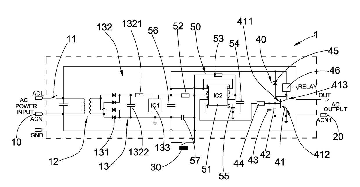
[0026]Referring to FIGS. 2 to 5 of the drawings, a magnetic switch controlled circuit 1 according a preferred embodiment of the present invention is illustrated. Broadly, the magnetic switch controlled circuit 1 may comprise a voltage input terminal 10, a voltage output terminal 20, a magnetic switch 30, a relay circuity 40 and a turn-off delay circuitry 50. The magnetic switch controlled circuit is for controlling the on / off of an electrical appliance, such as an electrical air curtain apparatus 80.

[0027]The voltage input terminal 10 may be adapted for electrically connecting to an external power source, such as an external Alternating Current (AC) power source.

[0028]The voltage output terminal 20 may be adapte...


PUM


Abstract

A magnetic switch controlled circuit for an electrical appliance includes a voltage input terminal, a voltage output terminal, a magnetic switch, a relay circuitry and a turn-off delay circuitry. When the magnetic switch detects a first change in the magnetic field from an idle status, the relay circuitry is configured to output an output voltage to the voltage output terminal so as to supply power to the electrical appliance. When the magnetic switch detects a second change in the magnetic field from the first change in the magnetic field, the turn-off delay circuitry is configured to control the relay circuitry to continue outputting the output voltage to the voltage output terminal for a predetermined period of time, the relay circuitry being switched off by the turn-off delay circuitry after the predetermined period of time elapses.

Description

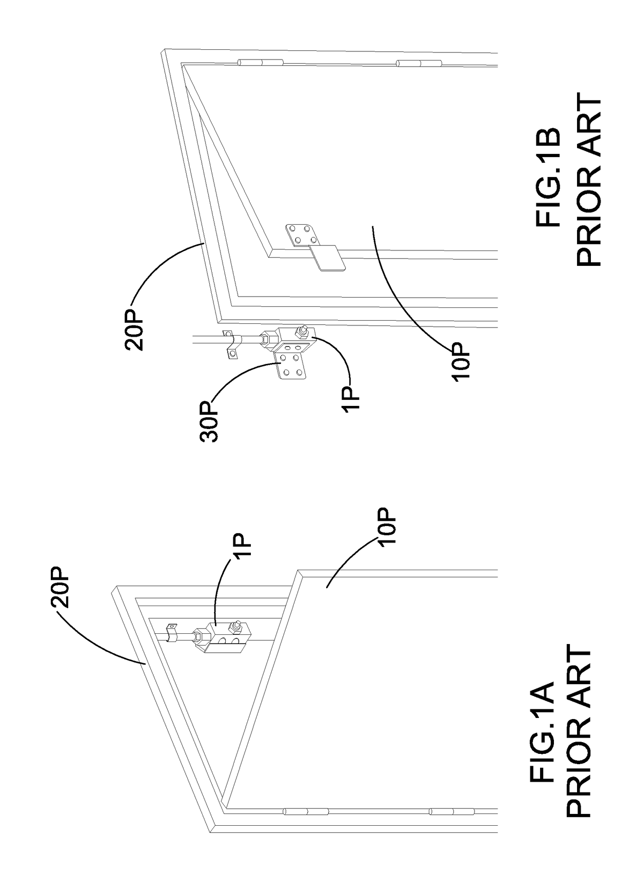
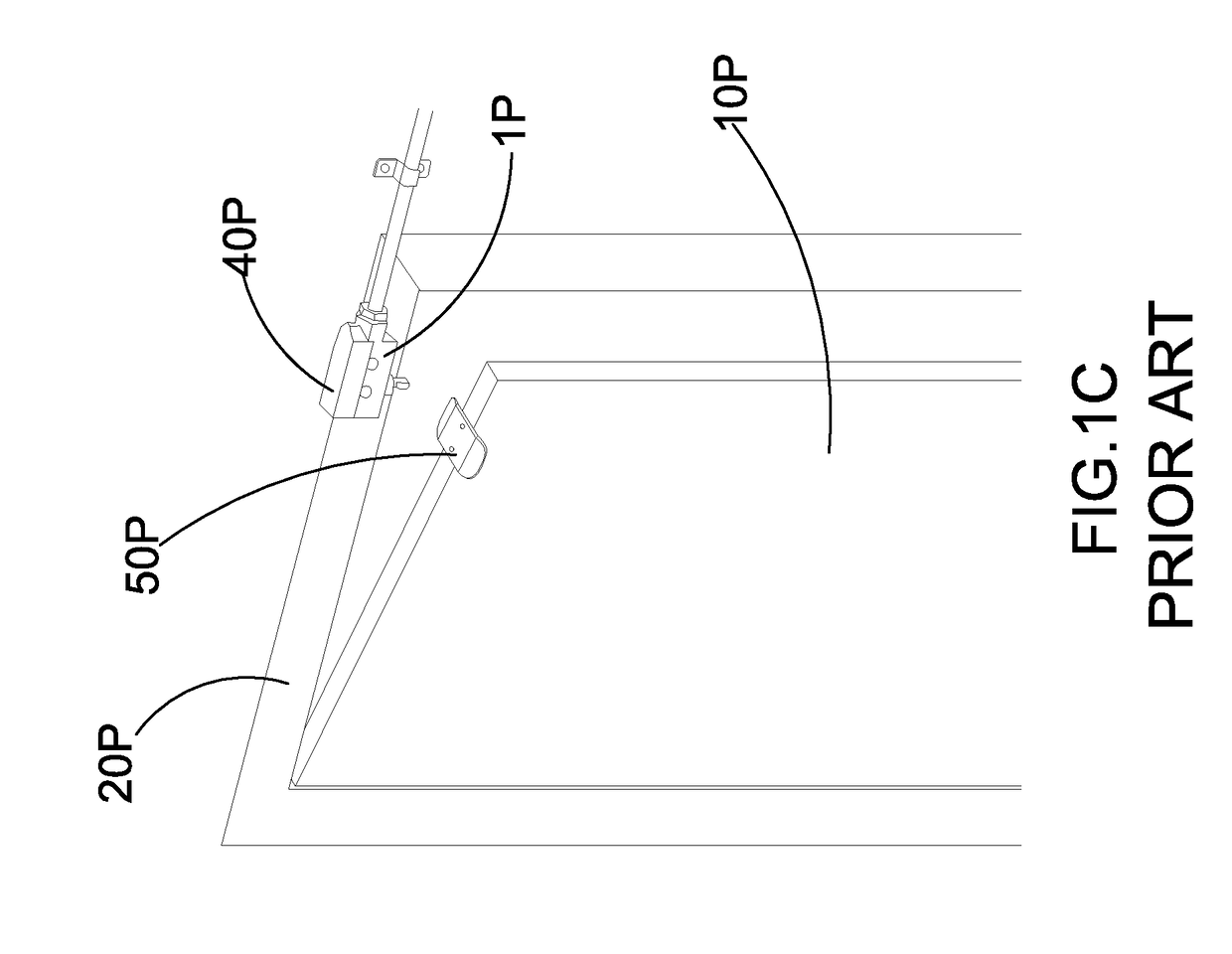
BACKGROUND OF THE PRESENT INVENTIONField of Invention[0001]The present invention relates to a switch circuit, and more particularly to a magnetic switch controlled circuit which may be used to switch on or switch off an electrical appliance such as an air curtain apparatus.Description of Related Arts[0002]Conventional mechanical switches, such as a mechanical switch used for controlling an air curtain apparatus, have widely been utilized. A conventional mechanical switch is usually bulky in size, and must be mounted on an object through some sorts of connectors or other mechanical tools. As a result, when the mechanical switch was improperly installed, it may not function at all. Moreover, conventional mechanical switches suffer from mechanical wear and tear when they have used for a certain period of time. In some situations, mechanical switches may be directly connected to high-voltage electrical components so that the wires connected to the mechanical switches must be specificall...

Claims


Application Information

Patent Timeline
Patent Type & Authority Applications(United States)
IPC IPC(8): H01H47/32H01H47/18
CPCH01H47/18H01H47/325F24F9/00F24F11/88F24F11/89F24F2009/005H01H36/0046
Inventor SITU, HUA FU
Owner SITU HUA FU
Learn More