
Brake Assistance System for Patient Handling Equipment

a technology for handling equipment and brakes, which is applied in the field of brake assistance systems for patient handling equipment, can solve the problems of tripping or otherwise losing control of the equipment and the potential consequences, low rolling resistance favorable while travelling along horizontal surfaces, and user's no means of decelerating or slowing the movement of a bed or a stretcher

Active Publication Date: 2018-07-05
ARJOHUNTLEIGH
View PDF4 Cites 10 Cited by
  • Summary
  • Abstract
  • Description
  • Claims
  • Application Information

AI Technical Summary

Benefits of technology

The patent describes a brake assist system for mobile patient handling equipment. The system includes sensors to detect when the equipment is on a slope and moving down the slope. The system automatically engages the brakes to slow down the equipment to a controlled speed to help the caregiver stop it. The system does not prevent the equipment from moving up the slope. The braus system works automatically without the need for the caregiver to do anything. The technical effect of this system is to make the equipment safer and easier to control when moving down slopes while maintaining a controlled speed.

Problems solved by technology

When operating such equipment along non-flat surfaces, such as down or up slopes, the user has to be prepared for the eventuality of slipping, tripping or otherwise losing control of the equipment and the potential consequences.
The low rolling resistance favorable while travelling along horizontal surfaces may be a disadvantage on any downward slope as the equipment may accelerate to a fairly high speed.
While such motorized propulsion systems can provide user assistance in moving a bed up slopes or over uneven surfaces, the user has no means for decelerating or slowing the movement of a bed or stretcher other than by manually applying the brake pedals and / or forcibly pulling / pushing on the bed or stretcher in a direction opposite of its trajectory / velocity.

Method used


Image

  • Brake Assistance System for Patient Handling Equipment
  • Brake Assistance System for Patient Handling Equipment
  • Brake Assistance System for Patient Handling Equipment

Examples


Embodiment Construction

[0036]In the field of mobile patient handling equipment such as beds, trolleys and patient lifts it is known to utilize a 5th wheel for steering and / or propulsion. Such systems most often rely on an input signal in the form of a user controlled throttle, a load cell sensing the amount of force applied by the user or a simple push button, all commanding the system to propel the equipment in a given direction. Other systems exist which rely on user input in the form of active brake force; for example, a system including a lever coupled via a wire to a brake arrangement to control speed, often referred to as a rollator. Both these type of system require the user to be an active part in the control loop. If the user fails to control the device, the system comes either to an abrupt halt or runs away from the user.

[0037]The systems disclosed herein addresses the aforementioned deficiencies and enable patient handling equipment to travel at a controlled and regulated speed down slopes, tak...


PUM


Abstract

A brake assist system for patient handling equipment such as a patient bed includes a drive wheel. The wheel includes a brake assist system operated by control of a controlled unit which is operable to sense tilt of the handling equipment and to apply partial breaking to the wheel when it is detected that the equipment is on a slope. The control unit controls a maximum speed of the equipment down the slope, in order to protect the patient and to assist a care worker. The control unit disengages the brake assist mechanism when it is detected that the equipment is on a horizontal surface.

Description

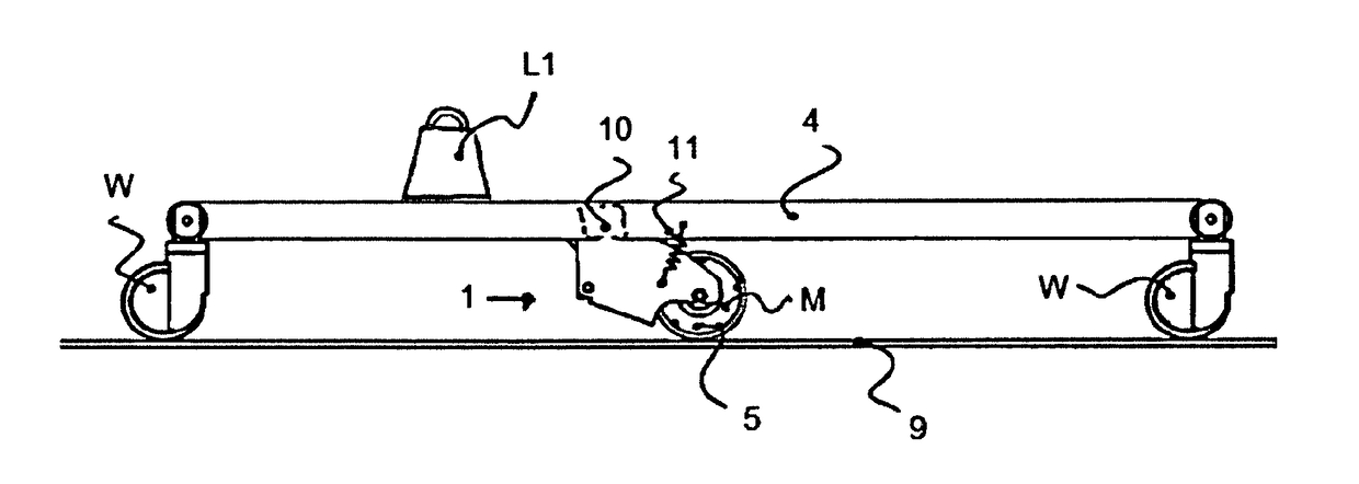
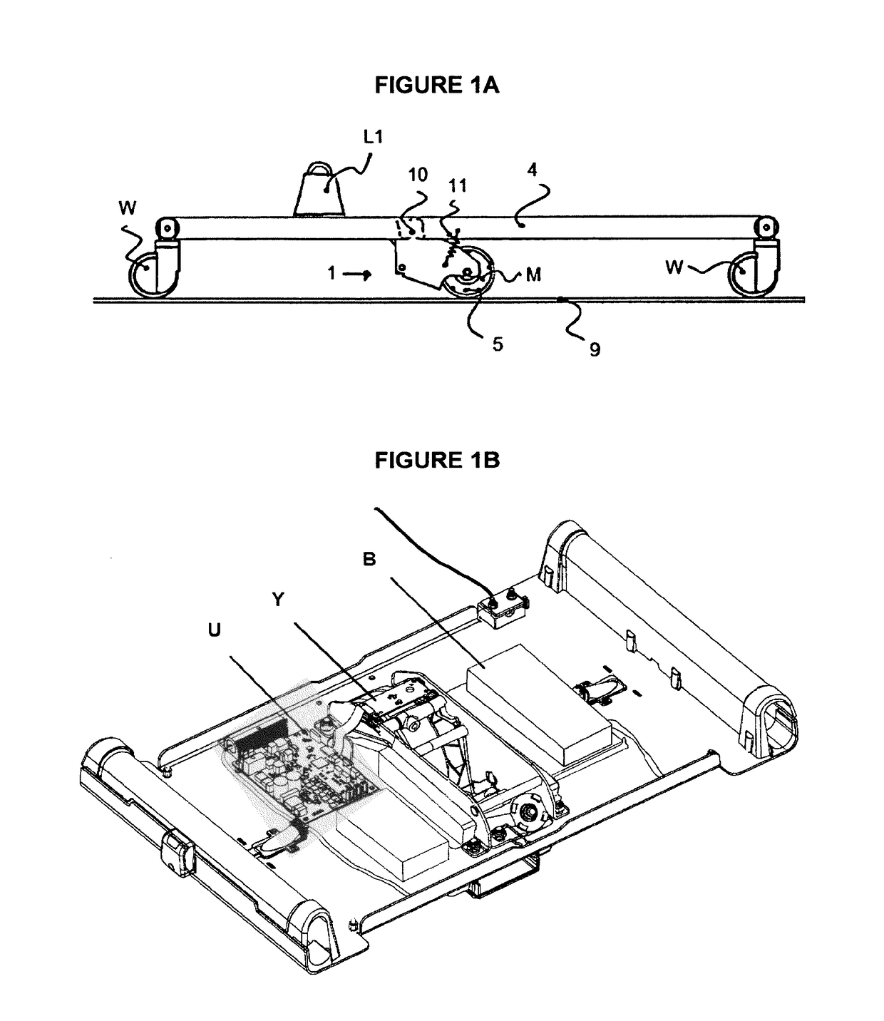
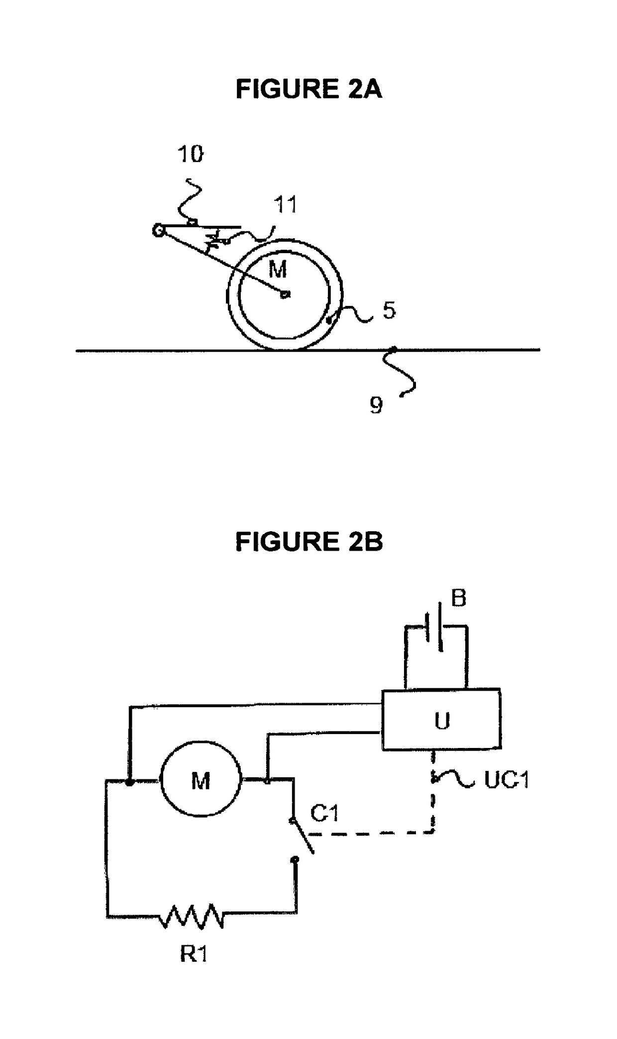
FIELD OF THE DISCLOSURE[0001]This disclosure relates to a brake assistance system for a patient handling equipment (powered or not) such as a medical bed, trolley / stretcher, patient lift, surgical table and other medical equipment incorporating a brake assistance system. In one embodiment the brake assistance system is incorporated into and / or operatively associated with a wheel system of the patient handling equipment.BACKGROUND OF THE DISCLOSURE[0002]Mobile patient handling equipment relies on castors having low rolling resistance, both in their direction of movement and in their ability to change direction, that is to swivel. This gives the patient handling equipment favorable abilities such as lowering the force it takes to move the patient handling equipment and its payload from one location to another.[0003]When operating such equipment along non-flat surfaces, such as down or up slopes, the user has to be prepared for the eventuality of slipping, tripping or otherwise losing ...

Claims


Application Information

Patent Timeline
IPC IPC(8): A61G1/02A61G7/05B60B33/00
CPCA61G1/0287A61G1/0275A61G7/0528B60B33/0094
Inventor JONSSON, JORGENALIM, MUSADJANSMITH, DANNYHOMBERG, ULFPETERSSON, DANIEL
Owner ARJOHUNTLEIGH
Learn More